MRI compatible implantable medical lead and method of making same

Inactive Publication Date: 2010-05-06
PACESETTER INC
View PDF8 Cites 41 Cited by
  • Summary
  • Abstract
  • Description
  • Claims
  • Application Information

AI Technical Summary

Problems solved by technology

Existing implantable medical leads for use with implantable pulse generators, such as neurostimulators, pacemakers, defibrillators or implantable cardioverter defibrillators (“ICD”), are prone to heating and induced current when placed in the strong magnetic (static, gradient and RF) fields of a magnetic reso

Method used


Image

  • MRI compatible implantable medical lead and method of making same
  • MRI compatible implantable medical lead and method of making same
  • MRI compatible implantable medical lead and method of making same

Examples


Embodiment Construction

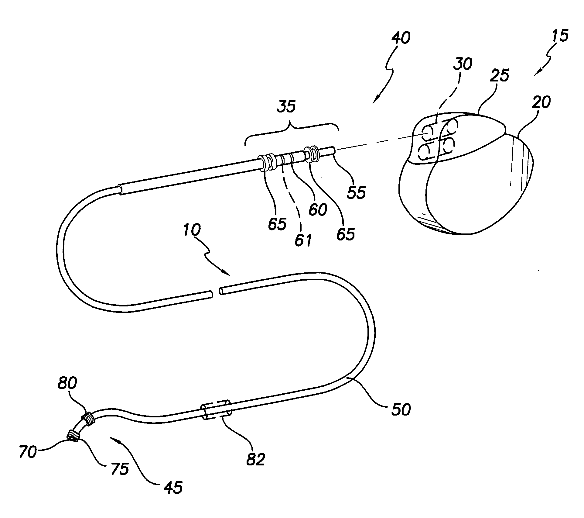
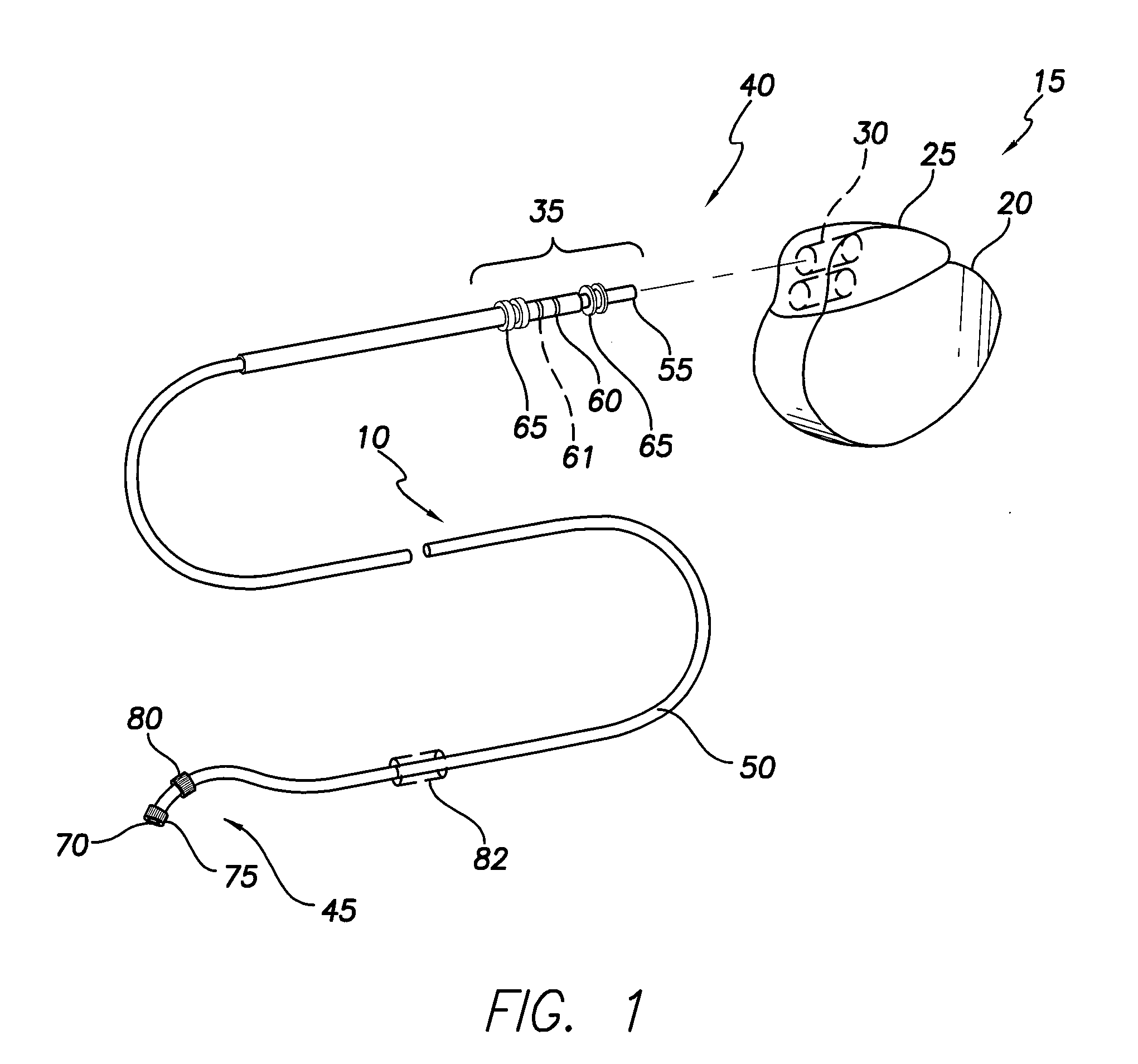
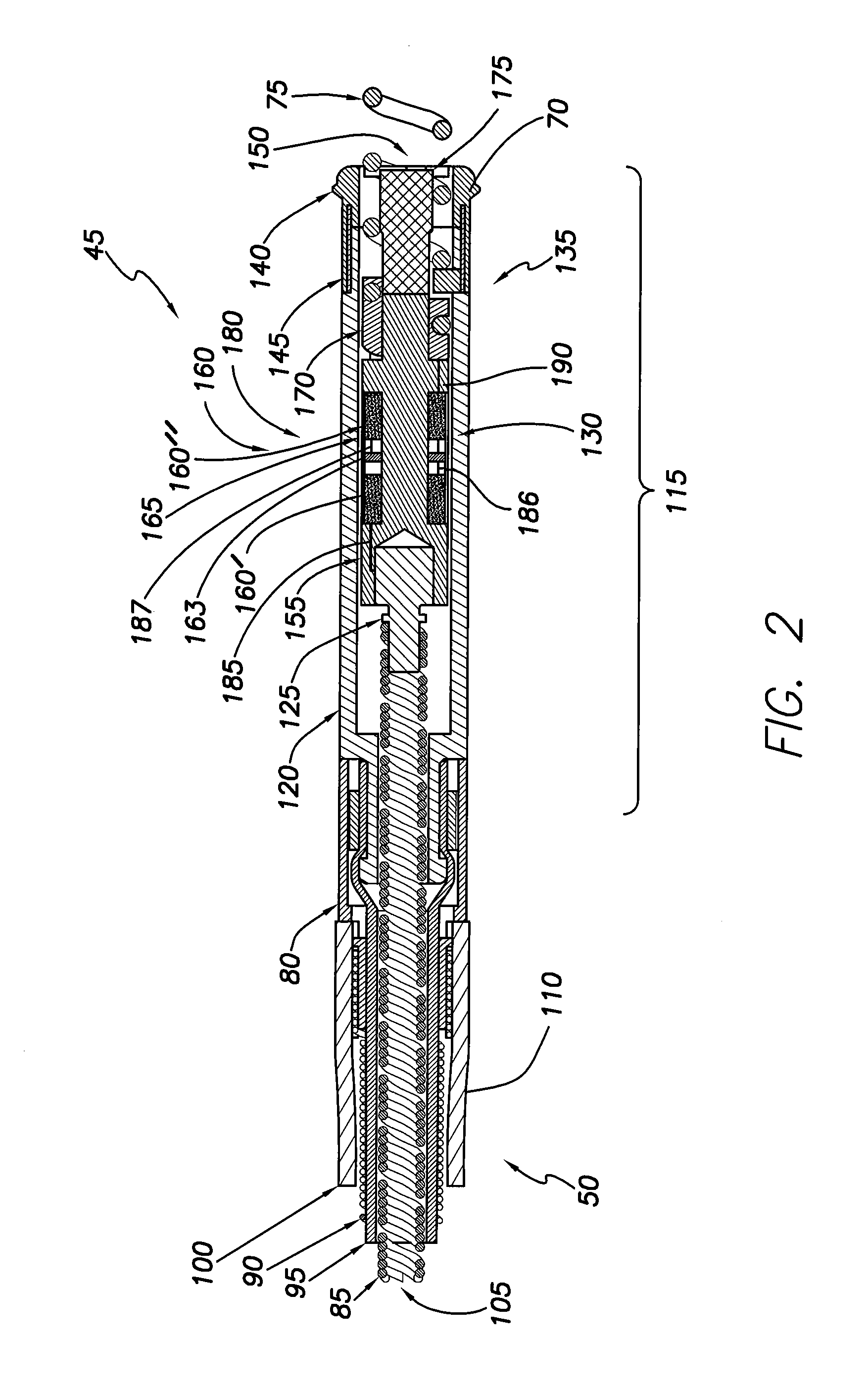
[0021]Disclosed herein is an implantable medical lead 10 employing a lumped inductor 160 near the distal end 45 of the lead 10. In one embodiment, the lumped inductor 160 may be partitioned or divided via a magnetic shielding layer (“shield”) 163 to at least partially magnetically decouple the inductor 160 into separate portions 160′, 160″ to provide high impedance at multiple MRI scan frequencies, for example, at both 64 MHz and 128 MHz, and, perhaps, even additional scan frequencies, each portion 160′, 160″ being tuned to have high impedance at a specific one of the multiple MRI scan frequencies. Thus, the lumped inductor 160 may be configured to have multiple, for example, two or more, self resonant frequencies (“SRF”). Thus, regardless of which type of MRI scan, for example, 1.5T and 3.0T, the patient undergoes, the lead 10 implanted in the patient will have high impedance, substantially reducing, if not eliminating, induced currents in the lead conductors 85, 90 and the associa...


PUM


Abstract

An implantable medical lead is disclosed herein. In one embodiment, the lead includes a body and an electrical pathway. The body may include a distal portion with an electrode and a proximal portion with a lead connector end. The electrical pathway may extend between the electrode and lead connector end and include a coiled inductor including a first portion and a second portion at least partially magnetically decoupled from the first portion. The first portion may include a first configuration having a first SRF. The second portion may include a second configuration different from the first configuration. The second configuration may have a second SRF different from the first SRF. For example, the first SRF may be near 64 MHz and the second SRF may be near 128 MHz.

Description

CROSS-REFERENCE TO RELATED APPLICATIONS[0001]This application is related to copending U.S. patent application Ser. No. ______, filed concurrently herewith, titled “MRI Compatible Implantable Medical Lead and Method of Making Same” (Attorney Docket No. A08P1043).FIELD OF THE INVENTION[0002]The present invention relates to medical apparatus and methods. More specifically, the present invention relates to implantable medical leads and methods of manufacturing such leads.BACKGROUND OF THE INVENTION[0003]Existing implantable medical leads for use with implantable pulse generators, such as neurostimulators, pacemakers, defibrillators or implantable cardioverter defibrillators (“ICD”), are prone to heating and induced current when placed in the strong magnetic (static, gradient and RF) fields of a magnetic resonance imaging (“MRI”) machine. The heating and induced current are the result of the lead acting like an antenna in the magnetic fields generated during a MRI. Heating and induced cu...

Claims


Application Information

Patent Timeline
IPC IPC(8): A61N1/05
CPCA61N1/05H01F17/00A61N1/086
Inventor MIN, XIAOYIMOULDER, J. CHRISTOPHERZHAO, YONG D.INDRAVUDH, VIROTEVIOHL, INGMAR
Owner PACESETTER INC
Why Eureka
Try Eureka