Multi-part pin remover for removing a pin or stud from a hole of a component

a technology of pin or stud and component, which is applied in the direction of metal-working equipment, metal-working tools, manufacturing tools, etc., can solve the problems of less secure friction fit, damage to the component, and damage in the opening region of the hole, so as to achieve positive and sufficiently reliable positive locking connection, unchangeable quality, and the effect of good sealing

Inactive Publication Date: 2010-05-13
SIEMENS AG
View PDF8 Cites 9 Cited by
  • Summary
  • Abstract
  • Description
  • Claims
  • Application Information

AI Technical Summary

Benefits of technology

[0012]In an expedient manner, the hook-shaped projection is insertable preferably almost free from play, that is with accuracy of fit, into a groove that is provided on the component. The wall thickness of the hook-shaped projection and the width of the groove are accordingly coordinated with one another. Consequently, there is an error-free alignment of the pin remover where the central longitudinal axis of the pin coincides with the pulling direction of the pin remover. In another advantageous development, the projection provided on the holder extends transversely to the pulling direction. This makes it possible for the holder not to be displaced relative to the component when the pin is being pulled out.
[0013]In particular, it is not possible for the component to tilt about the central axis of t...

Problems solved by technology

It has proved disadvantageous that when the pin is being pulled out, the holder or the pull rod can tilt relative to the axial direction of the pin, which can result in damage to the component when the pin is being released.
The damage can be widening in the region of the opening of the hole.
When a replacement pin is inserted, this damage can result in a less secure friction fit b...

Method used


Image

  • Multi-part pin remover for removing a pin or stud from a hole of a component
  • Multi-part pin remover for removing a pin or stud from a hole of a component
  • Multi-part pin remover for removing a pin or stud from a hole of a component

Examples


Embodiment Construction

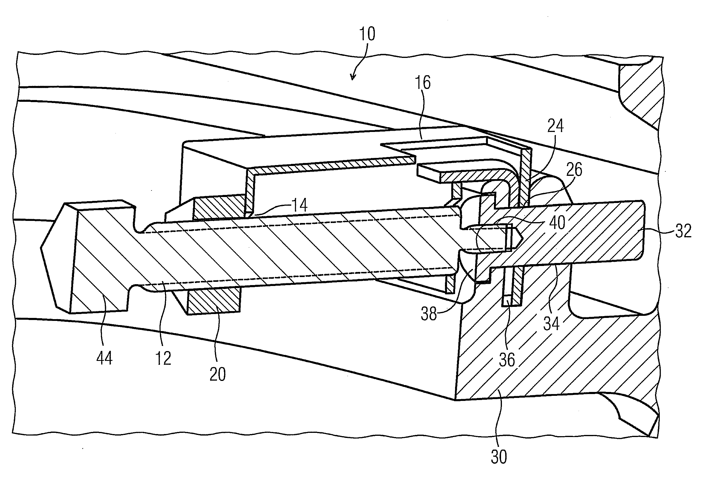
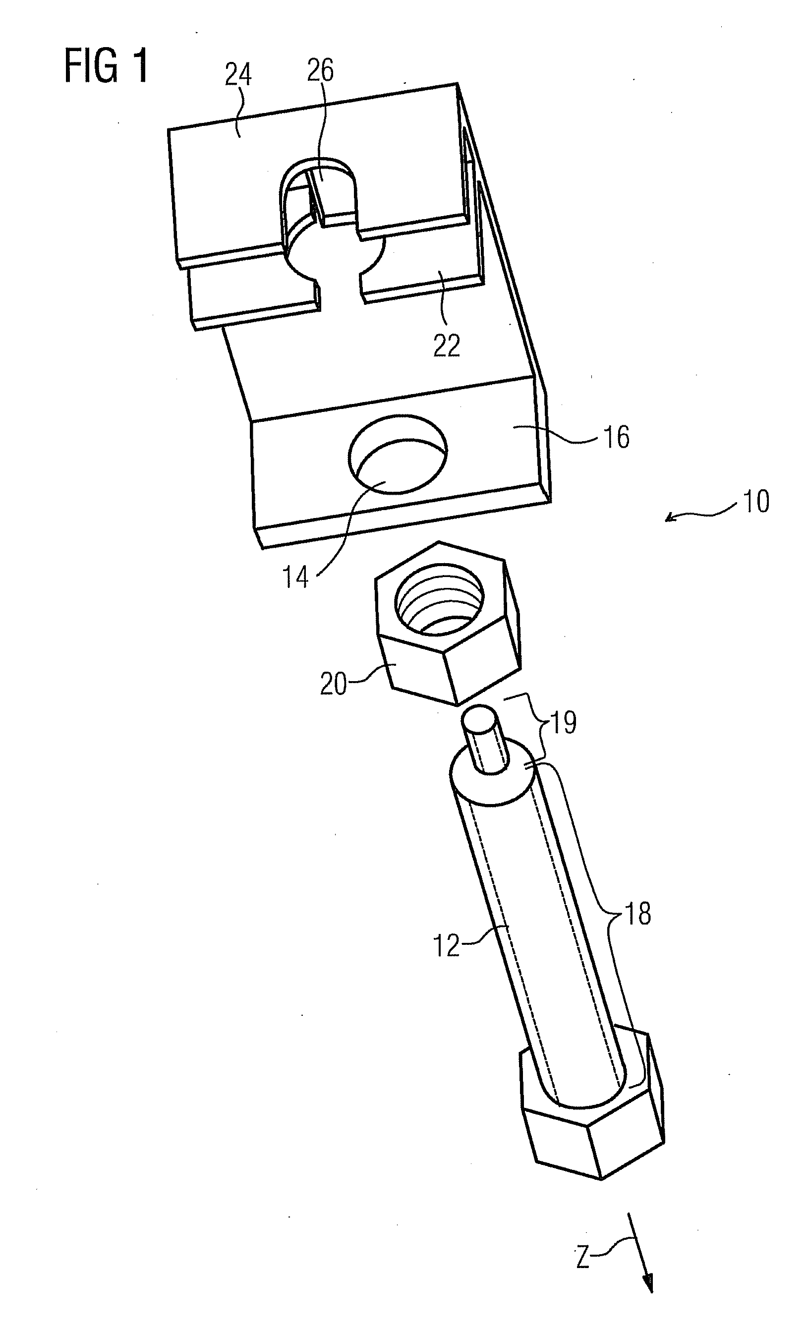
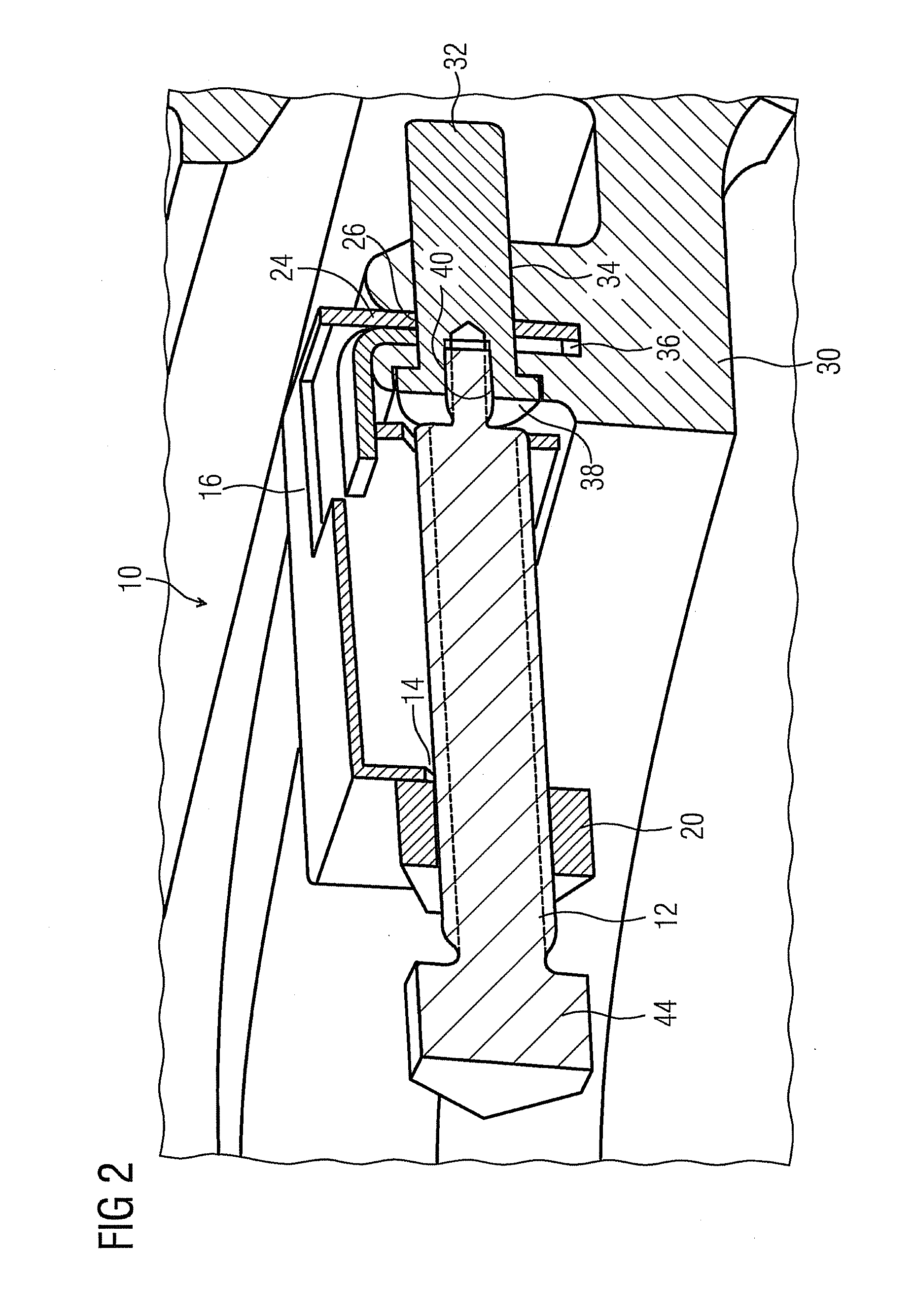
[0019]FIG. 1 shows an exploded representation of a multi-part pin remover 10 according to the invention for removing a pin or stud from a hole of a component. The component can be a rotor disc or a gas turbine, for example, as is made known in the European Patent Application with the official number of 07 000 381.9. Through this reference, the object disclosed in the European Patent Application with the official number of 07 000 381.9 is explicitly incorporated into this Patent Application and consequently becomes part of the disclosure of this Patent Application.

[0020]The pin remover 10 comprises a holder 16, into the opening 14 of which a pull rod 12 can be inserted. The pull rod 12 is provided with at least one first thread portion 18, to which a screw nut 20 can be screw-connected.

[0021]Along with the opening 14, the holder 16 comprises a contact face 22, which can be positioned in a planar manner against the surrounding area of the hole, from which the pin is to be removed. In ...


PUM

PropertyMeasurementUnit
Thicknessaaaaaaaaaa
Diameteraaaaaaaaaa
Areaaaaaaaaaaa

Abstract

A multi-part pin remover for removing a pin from a hole of a component is provided. A holder of the pin remover that is supported on the component is equipped with a projection that aligns the pin remover with respect to the component in order to reliably prevent any twisting of the pin when removing the pin from the hole.

Description

[0001]This application is the US National Stage of International Application No. PCT / EP2008 / 053263, filed Mar. 19, 2008 and claims the benefit thereof. The International Application claims the benefits of European Patent Office application No. 07007216.0 EP filed Apr. 5, 2007, both of the applications are incorporated by reference herein in their entirety.FIELD OF INVENTION[0002]The invention relates to a multi-part pin remover for removing a pin or stud from a hole of a component, said multi-part pin remover comprising a pull rod that is provided with a thread and a holder that accommodates the pull rod and can be supported on the component for releasing the pin from the component, wherein the pull rod is connectable in a positive locking manner to the pin to be released and, in the state connected to the pin, is displaceable in the pulling direction by rotating a screw nut that is supported on the holder.BACKGROUND OF INVENTION[0003]Multi-part pin removers for removing a pin or st...

Claims


Application Information

Patent Timeline
IPC IPC(8): B23P19/04
CPCB25B27/023B25B27/04Y10T29/53909Y10T29/53848Y10T29/53817Y10T29/53857
Inventor BILSTEIN, BJOERNSCHRODER, PETER
Owner SIEMENS AG
Why Eureka
Try Eureka