Differential head having a balanced output and method of manufacturing thereof

a technology of differential heads and outputs, applied in the field of differential types of magnetoresistive effects elements, can solve the problems of reducing thickness, reducing gap length gs, and achieving the effect of increasing track width

Inactive Publication Date: 2010-05-13
WESTERN DIGITAL TECH INC
View PDF12 Cites 5 Cited by
  • Summary
  • Abstract
  • Description
  • Claims
  • Application Information

AI Technical Summary

Benefits of technology

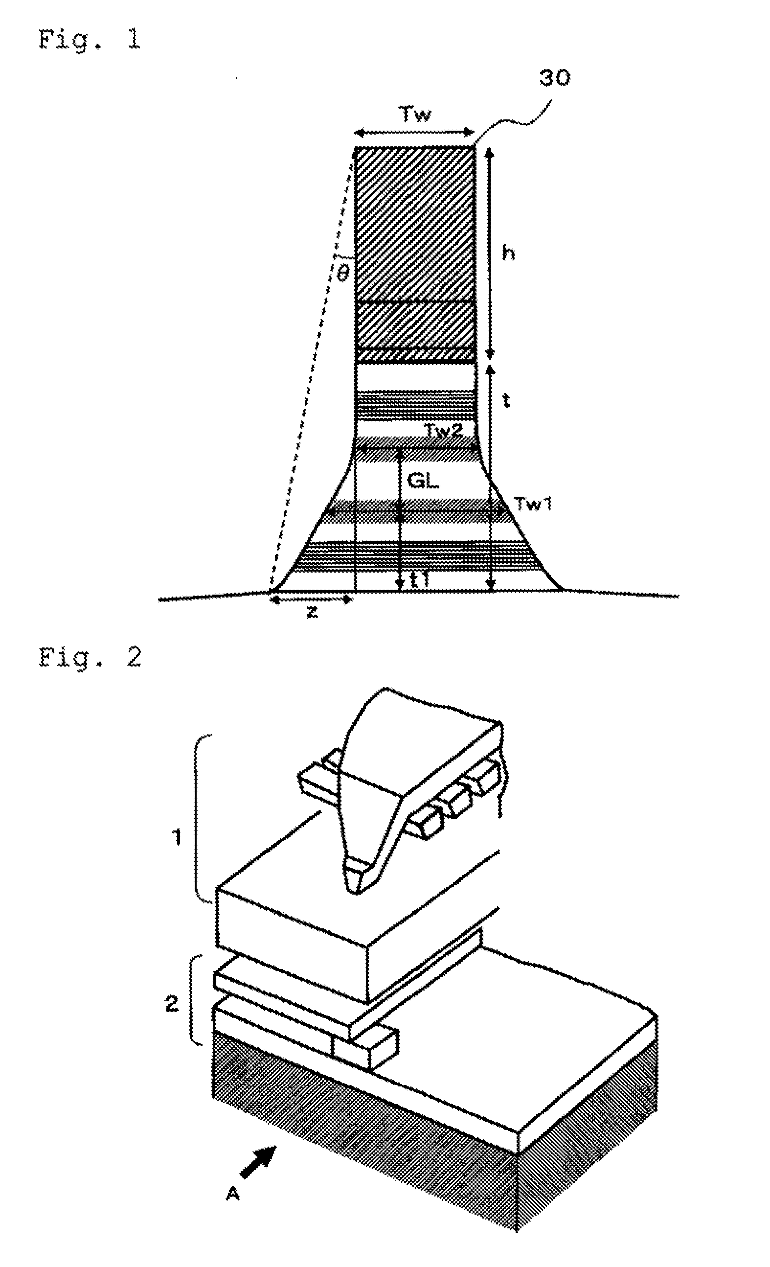
[0011]According to one embodiment, a differential-type magnetic read head comprises a differential-type magneto-resistive-effect film formed on a substrate and a pair of electrodes for applying current to the differential-type magneto-resistive-effect film in a direction perpendicular to a film plane of the film. The differential-type magneto-resistive-effect film includes a first stacked film having: a first pinned layer; a first intermediate layer; and a first free layer. The differential-type magneto-resistive-effect film also includes a second stacked film formed on the first stacked film, the second stacked film having: a second pinned layer; a second intermediate layer; and a second free layer. A side face in a track width direction of the differential-type magneto-resistive-effect film is shaped to have an inflection point at an intermediate position in a thickness direction of the differential-type magneto-resistive-effect film, and the side face is shaped to be approximately vertical to the substrate in an upward direction of the substrate from the inflection point. Also, the side face is shaped to be gradually increased in track width as approaching the substrate in a downward direction of the substrate from the inflection point.

Problems solved by technology

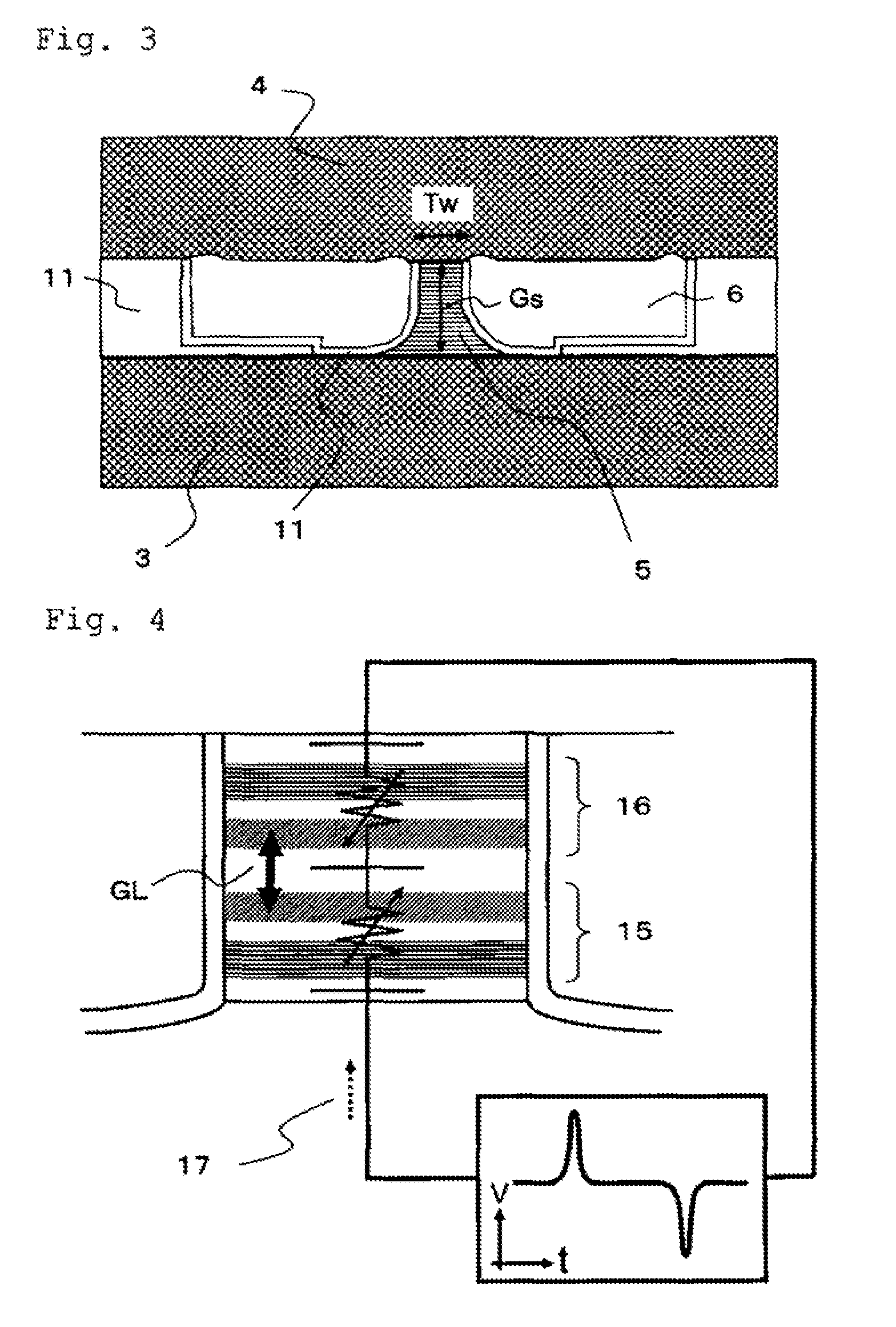
However, gap length Gs approximately reaches a technological limit of size reduction unlike the track width Tw.
While the possibility of improving resolution in the bit direction by a differential-type read head structure for HDD is previously known, the possibility has not been applied in practice because a manufacturing process of the head is too difficult to perform consistently.
However, such a reduction in thickness will soon reach the described technical limit.
In addition, the following problems in a manufacturing process of the head exist currently.
A first problem of current techniques is that film characteristics of an upper element deposited later tend to be degraded, which is due to continuous deposition of the two elements.
A second problem of current techniques is that element characteristics tend to be degraded during an ion milling step for processing a sensor film including the deposited, two elements to have a desired track width.
In the differential-type structure, since total thickness of the two elements, namely, thickness two times as large as previous thickness is subjected to processing, there is a high probability that element characteristics are degraded due to damage to the end face of the element exposed during processing, or due to redeposit caused by ion milling.

Method used


Image

  • Differential head having a balanced output and method of manufacturing thereof
  • Differential head having a balanced output and method of manufacturing thereof
  • Differential head having a balanced output and method of manufacturing thereof

Examples


Embodiment Construction

[0054]The following description is made for the purpose of illustrating the general principles of the present invention and is not meant to limit the inventive concepts claimed herein. Further, particular features described herein can be used in combination with other described features in each of the various possible combinations and permutations.

[0055]Unless otherwise specifically defined herein, all terms are to be given their broadest possible interpretation including meanings implied from the specification as well as meanings understood by those skilled in the art and / or as defined in dictionaries, treatises, etc.

[0056]It must also be noted that, as used in the specification and the appended claims, the singular forms “a,”“an” and “the” include plural referents unless otherwise specified.

[0057]In one general embodiment, a differential-type magnetic read head comprise a differential-type magneto-resistive-effect film formed on a substrate; and a pair of electrodes for applying c...


PUM

PropertyMeasurementUnit
track widthaaaaaaaaaa
widthaaaaaaaaaa
gap length Gsaaaaaaaaaa

Abstract

In one embodiment, a differential-type magnetic read head includes a differential-type magneto-resistive-effect film formed on a substrate, and a pair of electrodes for applying current in a direction perpendicular to a film plane of the film. The film includes a first and second stacked film, each having a pinned layer, an intermediate layer, and a free layer, with the second stacked film being formed on the first stacked film. A side face in a track width direction of the film is shaped to have an inflection point at an intermediate position in a thickness direction of the film, and the side face is shaped to be approximately vertical to the substrate in an upward direction of the substrate from the inflection point. Also, the side face is shaped to be gradually increased in track width as approaching the substrate in a downward direction of the substrate from the inflection point.

Description

RELATED APPLICATIONS[0001]The present application claims priority to a Japanese Patent Application filed Nov. 10, 2008, under Appl. No. 2008-287395, which is incorporated herein by reference.FIELD OF THE INVENTION[0002]The present invention relates to magnetic recording / reproducing devices, and specifically to a differential-type magneto-resistive-effect element that is used as a sensor for a magnetic read head mounted on a magnetic recording / reproducing device.BACKGROUND OF THE INVENTION[0003]In storage (recording) devices used for data and information systems, semiconductor memories and magnetic memories are generally used for data storage. For applications specifying short access times, semiconductor memories are generally used in internal storage devices. For applications specifying huge capacity and non-volatility, hard disk drives (HDDs) are generally used which employ magnetic disks as external storage devices. Storage capacity is an important index to indicate the capability...

Claims


Application Information

Patent Timeline
Patent Type & Authority Applications(United States)
IPC IPC(8): G11B5/127
CPCG11B5/398G11B5/3163
Inventor YASUI, KANSHIIMOTO, MASATONAKAGAWA, TAKESHIKATADA, HIROYUKIYOSHIDA, NOBUOHOSHIYA, HIROYUKI
Owner WESTERN DIGITAL TECH INC
Why Eureka
Try Eureka