
MIMO antenna system

a technology of antenna system and mirror, which is applied in the field of communication devices, can solve problems such as space on the access poin

Active Publication Date: 2010-05-13
CAMBIUM NETWORKS
View PDF96 Cites 82 Cited by
  • Summary
  • Abstract
  • Description
  • Claims
  • Application Information

AI Technical Summary

Benefits of technology

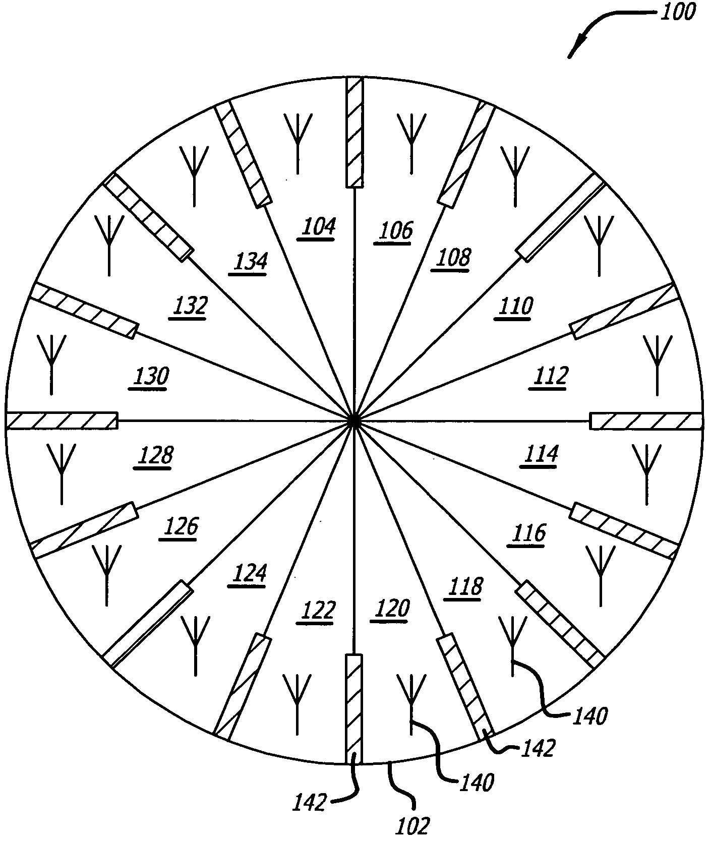
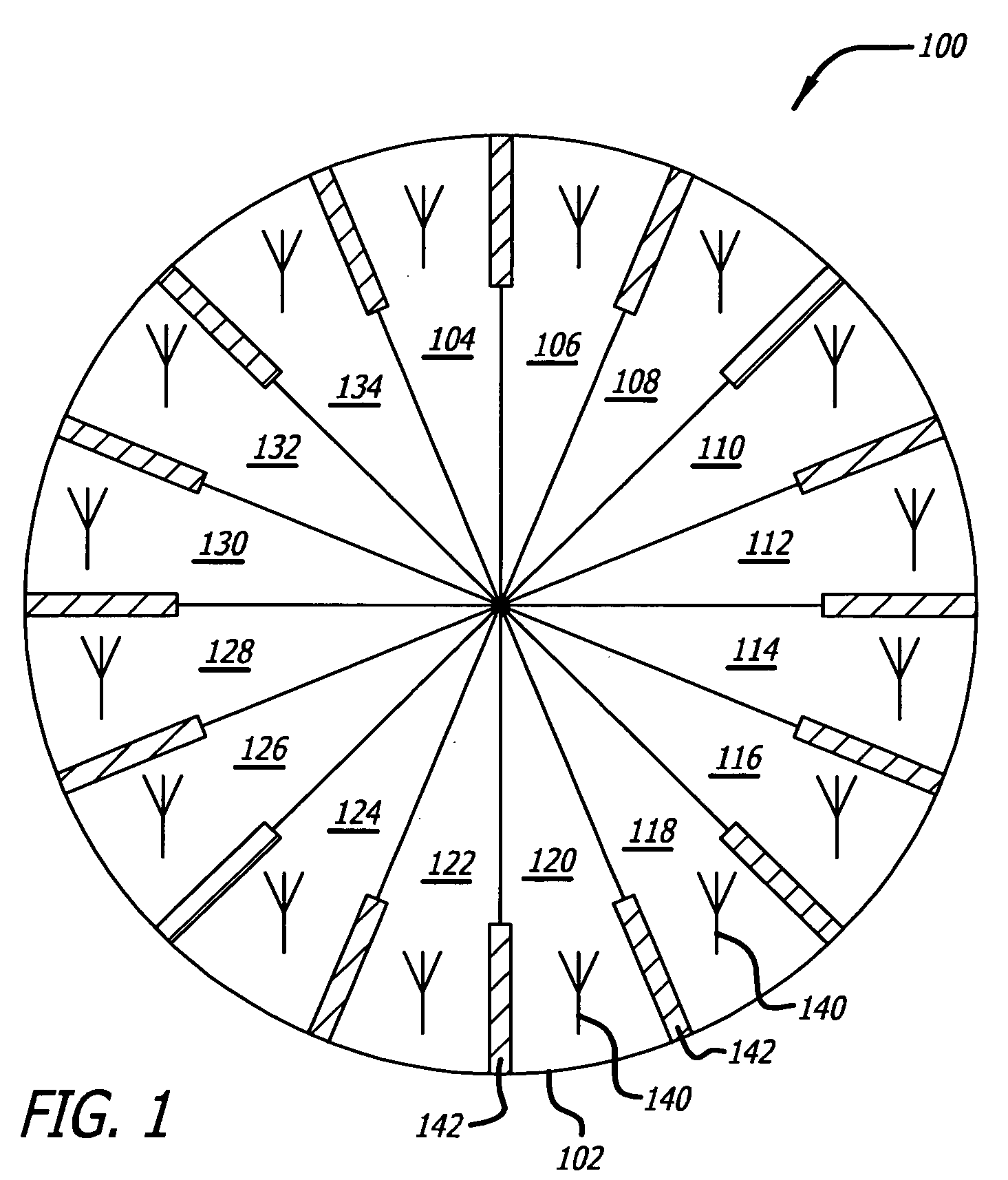
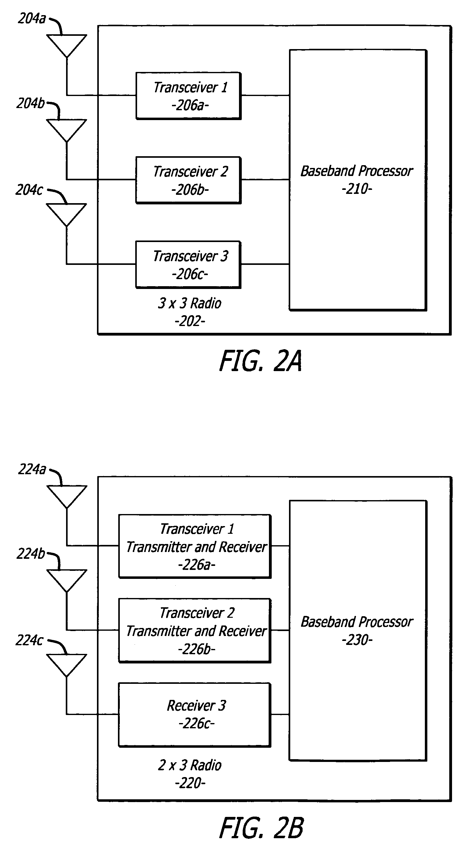
The patent describes a wireless local area network (WLAN) antenna array and an RF sub-system that provide 360 degrees of coverage when all available connectors are connected to corresponding RF PCBs. The WLANAA includes a circular housing with multiple radial sectors, each containing at least one radio and multiple MIMO antennas. The RF sub-system includes an RF PCB with at least one radio and multiple antenna PCBs mounted along its edge. The technical effects of this invention include improved wireless communication coverage and more efficient use of antenna space.

Problems solved by technology

The use of multiple antennas may create problems with space on the access point, particularly when the access point uses multiple radios.

Method used


Image

  • MIMO antenna system
  • MIMO antenna system
  • MIMO antenna system

Examples


Embodiment Construction

[0034]In the following description of example embodiments, reference is made to the accompanying drawings that form a part of the description, and which show, by way of illustration, specific example embodiments in which the invention may be practiced. Other embodiments may be utilized and structural changes may be made without departing from the scope of the invention.

[0035]A wireless local area network (“WLAN”) antenna array (“WLANAA”) is disclosed. The WLANAA may include a circular housing having a plurality of radial sectors and a plurality of primary antenna elements. Each individual primary antenna element of the plurality of primary antenna elements may be positioned within an individual radial sector of the plurality of radial sectors.

[0036]In general, the WLANAA is a multi-sector antenna system that has high gain and radiates a plurality of radiation patterns that “carve” up the airspace into equal sections of space or sectors with a certain amount of pattern overlap to ass...


PUM


Abstract

A wireless local area network (“WLAN”) antenna array (“WLANAA”) includes a circular housing having a plurality of radial sectors and a plurality of primary antenna elements configured as Multiple-Input, Multiple-Output (MIMO) antennas. Each primary antenna element, which includes multiple antennas connected to a single radio, being positioned within a radial sector of the plurality of radial sectors.

Description

BACKGROUND OF THE INVENTION[0001]1. Field of the Invention[0002]This invention relates generally to communication devices and more particularly to antennas for Multiple-Input, Multiple-Output (MIMO) media access controllers.[0003]2. Related Art[0004]The use of wireless communication devices for data networking is growing at a rapid pace. Data networks that use “WiFi” (“Wireless Fidelity”), also known as “Wi-Fi,” are relatively easy to install, convenient to use, and supported by the IEEE 802.11 standard. WiFi data networks also provide performance that makes WiFi a suitable alternative to a wired data network for many business and home users.[0005]WiFi networks operate by employing wireless access points that provide users, having wireless (or “client”) devices in proximity to the access point, with access to varying types of data networks such as, for example, an Ethernet network or the Internet. The wireless access points include a radio that operates according to one of three sta...

Claims


Application Information

Patent Timeline
Patent Type & Authority Applications(United States)
IPC IPC(8): H04B7/04
CPCH01Q21/24H01Q21/205
Inventor HARTENSTEIN, ABRAHAM
Owner CAMBIUM NETWORKS
Learn More