Integrated MIMO antenna system

a technology of integrated antennas and mimo, which is applied in the field of integrated antenna systems, can solve problems such as the complicated design process of antennas, and achieve the effects of improving consistency across a large production lot, high degree of accuracy, and improving control over antenna spacing and orientation

Active Publication Date: 2013-12-05
TAOGLAS GROUP HLDG LTD
View PDF11 Cites 42 Cited by
  • Summary
  • Abstract
  • Description
  • Claims
  • Application Information

AI Technical Summary

Benefits of technology

[0010]In certain embodiments, a single integrated antenna assembly is provided comprising multiple antenna elements within a multi-input multi-output (MIMO) antenna system, wherein the spacing and orientation of each antenna element is maintained to a high degree of accuracy. The antennas are fabricated on a single substrate using a photo etching technique for providing improved control over antenna spacing and orientation within a production environment and maintaining improved consistency across a large production lot.
[0011]In one embodiment of the present invention, a baseline antenna design is duplicated at set spacings on a single thin flexible substrate (Flexible Printed Circuit, or “FPC”). The photo-etching technique used to fabricate FPCs provides a much higher degree of accuracy for inter-element spacing in the MIMO antenna system when compared to the individual placement of discrete antennas. In this regard, the orientation of the antenna elements in relation to the other antennas in the system is accurately set during the process where the artwork for the photo-etching is designed.
[0012]In another embodiment, a rigid substrate can be used to fabricate the antenna elements of the MIMO antenna system. The rigid substrate provides a self-supporting antenna assembly that can be attached to the portable electronic device. As with the FPC fabrication technique, the spacing and inter-element orientation can be very accurately maintained by using the photo-etching technique.

Problems solved by technology

The antenna design process is complicated by the multiple frequency bands that many MIMO antenna systems are required to cover.

Method used


Image

  • Integrated MIMO antenna system
  • Integrated MIMO antenna system
  • Integrated MIMO antenna system

Examples


Embodiment Construction

[0029]In the following description, for purposes of explanation and not limitation, details and descriptions are set forth in order to provide a thorough understanding of the present invention. However, it will be apparent to those skilled in the art that the present invention may be practiced in other embodiments that depart from these details and descriptions.

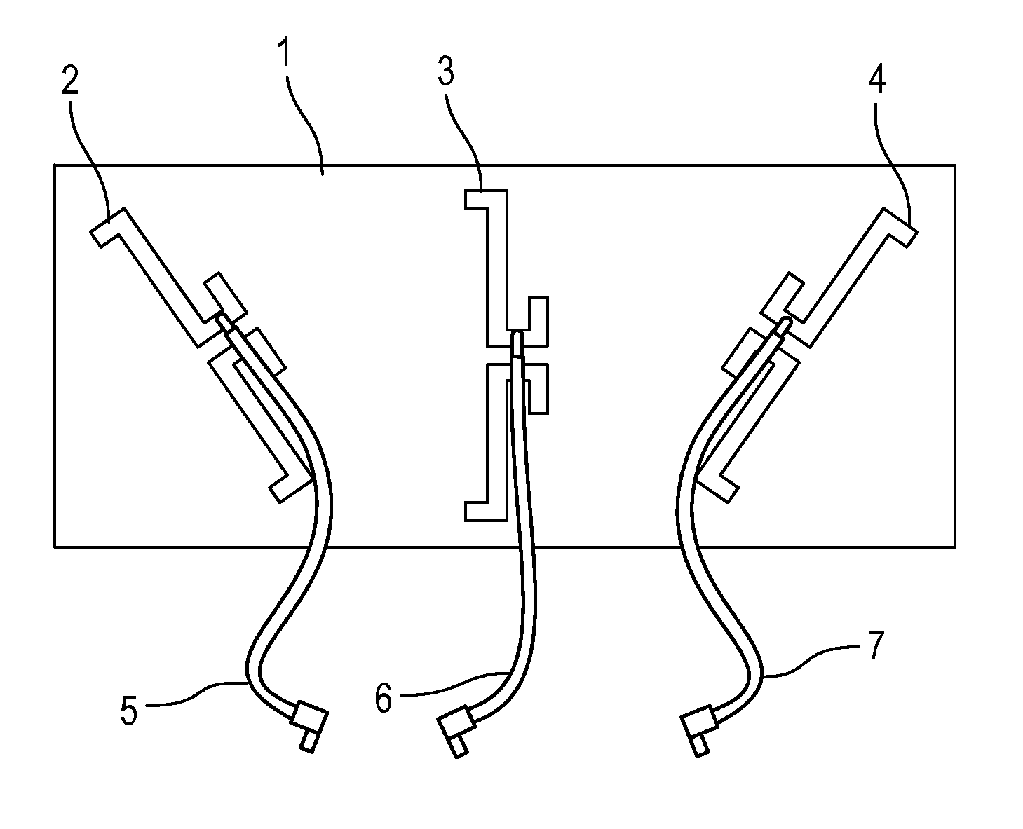
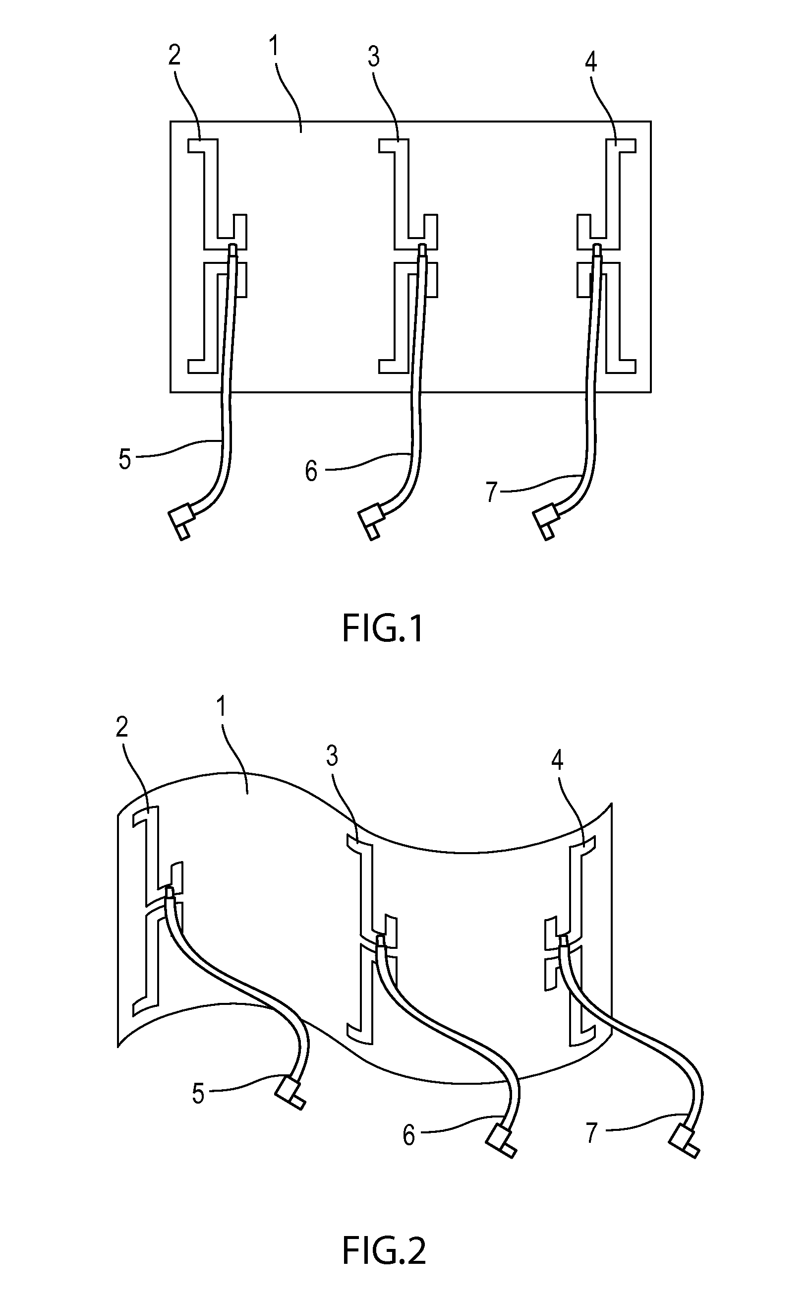
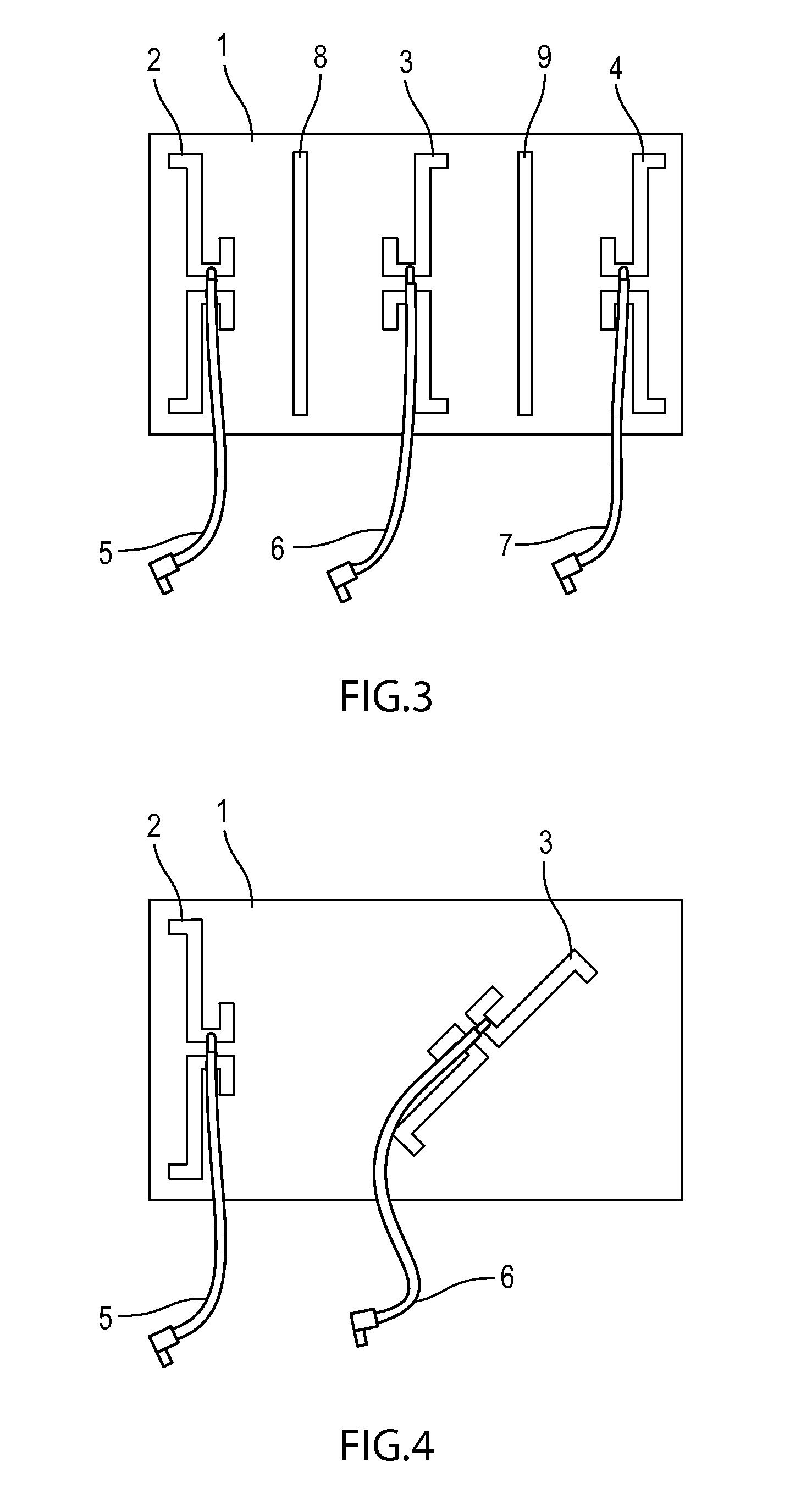
[0030]In a general embodiment, the invention provides a multi-input multi-output (MIMO) antenna system comprising a plurality of antenna elements disposed on a single substrate. The plurality of antenna elements are optimally positioned and spaced apart from one another to maintain high isolation and low pattern correlation therebetween. In order to accurately position and space the antenna elements, a photo-etching technique is used to fabricate the antennas onto the substrate.

[0031]Within the general embodiment, the MIMO antenna system comprises a first antenna element and a second antenna element being optimally positioned...


PUM

PropertyMeasurementUnit
frequencyaaaaaaaaaa
flexibleaaaaaaaaaa
angleaaaaaaaaaa

Abstract

An integrated MIMO antenna system is described wherein multiple antennas are fabricated on a single substrate. Antenna spacing and alignment is enhanced and controlled to a finer degree than with conventional discrete antenna fabrication techniques. Rotation of one or multiple antennas in relation to the other antennas in the system can be performed to within the accuracy of current photo-etching techniques. Metalized traces can be designed and etched on the single substrate and positioned between antenna elements to enhance inter-element isolation. The integrated MIMO antenna system can be fabricated on flexible printed circuit (FPC) material, or can be fabricated on rigid metallized substrate such as common FR4 materials. Portions of one or multiple antenna elements can be photo-etched on opposite sides of the substrate to provide an additional degree of freedom in terms of antenna placement, spacing, and rotation angle.

Description

BACKGROUND OF THE INVENTION[0001]1. Field of the Invention[0002]This invention relates to antenna systems; and more particularly to an integrated antenna system adapted for multi-input multi-output (MIMO) operation.[0003]2. Description of the Related Art[0004]In view of continuous improvements within the field of wireless communication technology, the trend in the tele-communication industry is to move to 4th generation, or 4G communication systems, for increased data rate requirements. The improved data rates achieved by 4G communication systems require multiple antennas on one or both ends of the communication link. This Multiple Input Multiple Output (MIMO) protocol and modulation scheme commonly requires multiple antennas operating in the same frequency band to be integrated into portable as well as stationary communication devices. The multiple antennas situated in the portable electronic devices, such as laptop computers, mobile phones, and personal digital assistants (PDAs) m...

Claims


Application Information

Patent Timeline
Patent Type & Authority Applications(United States)
IPC IPC(8): H01Q21/28H01G4/33H01B13/00
CPCH01Q9/285H01Q21/28
Inventor O'SHEA, DERMOTQUINLAN, RONAN
Owner TAOGLAS GROUP HLDG LTD
Why Eureka
Try Eureka