
High-speed two-way point-to-point transmission

a transmission and point-to-point technology, applied in power management, electrical equipment, multi-antenna systems, etc., can solve the problems of not being able to focus on mimo technology, and the newness of mimo technology, so as to achieve the maximum signal-to-noise ratio of each signal

Inactive Publication Date: 2006-02-28
AMERICAN TELEPHONE & TELEGRAPH CO
View PDF8 Cites 40 Cited by
  • Summary
  • Abstract
  • Description
  • Claims
  • Application Information

AI Technical Summary

Benefits of technology

[0004]If desired, techniques such as channel coding, dual polarization, adaptive receiver combining and adaptive power control can be included in a system embodying the principles of the invention. Such techniques would allow even greater data rates to be achieved than a system embodying the principles of the invention but not having those additional features. Indeed, we have found that by using a 2×2 MIMO system, pursuant to the principles of the present invention, in conjunction with such other techniques, it is possible to achieve OC-48 rates with minimal impact on existing services, with very high spectral efficiencies (specifically up to 10 b / s / Hz) over point-to-point links of, for example, about 1.5 to 8 kilometers with very high reliability (99.999%) corresponding to a bit error rate of 10−12.
[0006]Given such considerations, it is not surprising that it remained for the present inventors to recognize that MIMO techniques could be advantageously used in a high-data-rate point-to-point environment—one that is quite different from the cellular environment. For example, unlike in the cellular environment, a point-to-point path exhibits virtually no multipath diversity. We have recognized, however, that effects other than scattering can be looked to to provide the necessary diversity. In particular, we have recognized that spatial diversity is a form of diversity that can be realistically achieved in systems of the type in question by providing appropriate separation of the transmit antennas from one another and / or of the receive antennas from one another. Thus we have realized that the multipath diversity that is so crucial for effective implementation of MIMO in the cellular environment is not necessary for the point-to-point environment. In particular, for links of about 1.5 to 8 kilometers, the distance between transmit antennas and / or between receive antennas can be in the range of about 1 to 10 meters for systems operating at carrier wavelengths of about 24 millimeters, corresponding to carrier frequencies at about 12.45 GHz. Such antenna spacing makes it practical to install the MIMO antennas and their associated cabling on a building rooftop or similar structure.
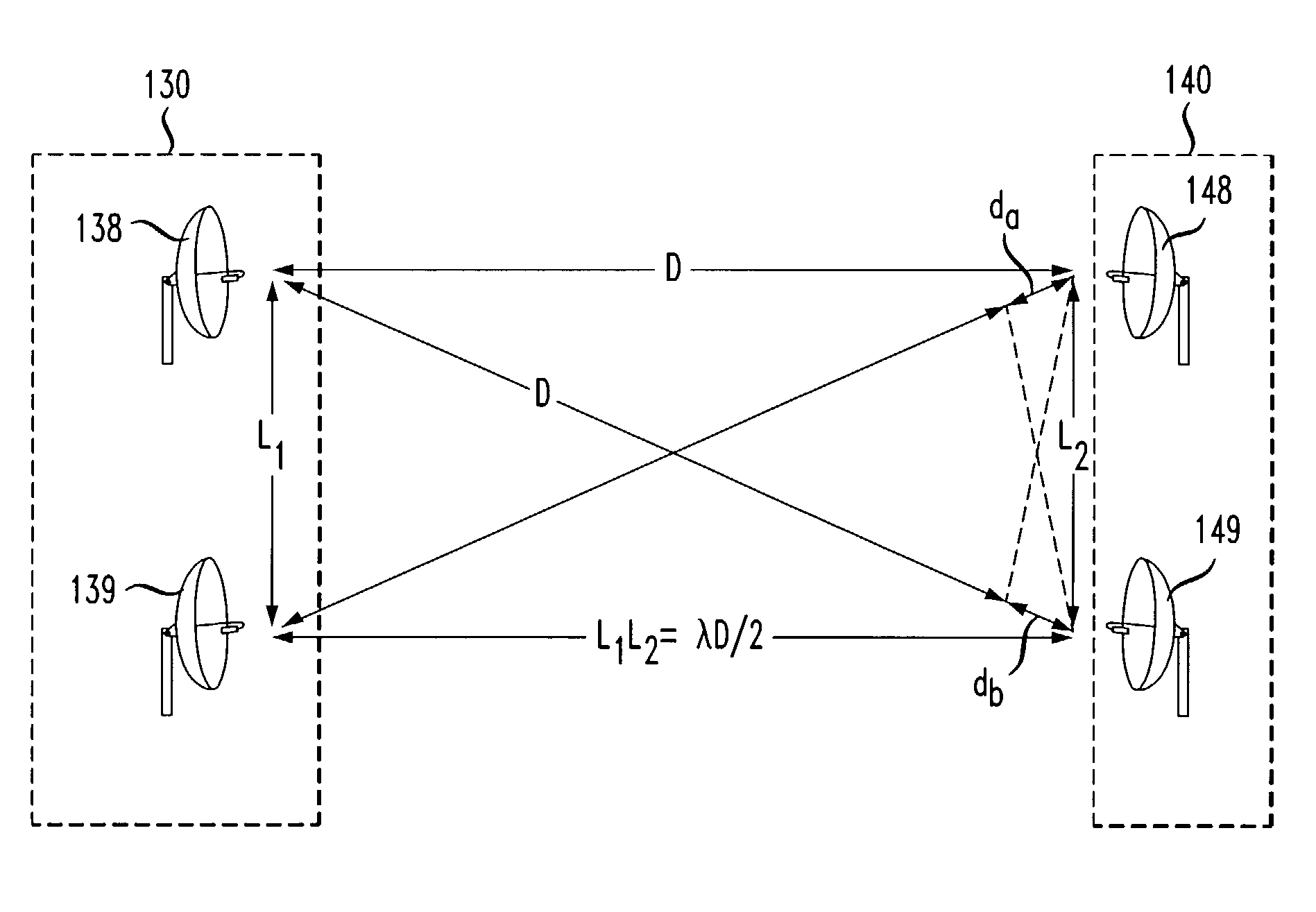
[0008]Particular embodiments of the invention utilize a 2×2 MIMO system—that is, a MIMO system having two transmit antennas and two receive antennas. First and second versions of the signal transmitted from one of the transmit antennas arrive at respective ones of the receive antennas over different-length paths, the difference in path length being a distance da. Similarly, first and second versions of the signal transmitted from the other one of the transmit antennas arrive at respective ones of the receive antennas over different-length paths, that difference in path length being an amount db. It is advantageous for the four antennas to be arranged in such a way that the sum of da and db is at least close, if not exactly equal, to an odd multiple of half the carrier wavelength, λ, i.e., λ / 2, 3λ / 2, 5λ / 2, etc. Meeting this criterion maximizes the signal-to-noise ratio of each signal being recovered when canceling out the other signal.

Problems solved by technology

MIMO technology is not new.
However, the focus of those working on MIMO technology has not been point-to-point applications, but mobile applications such as cellular telephony.

Method used


Image

  • High-speed two-way point-to-point transmission
  • High-speed two-way point-to-point transmission
  • High-speed two-way point-to-point transmission

Examples


Embodiment Construction

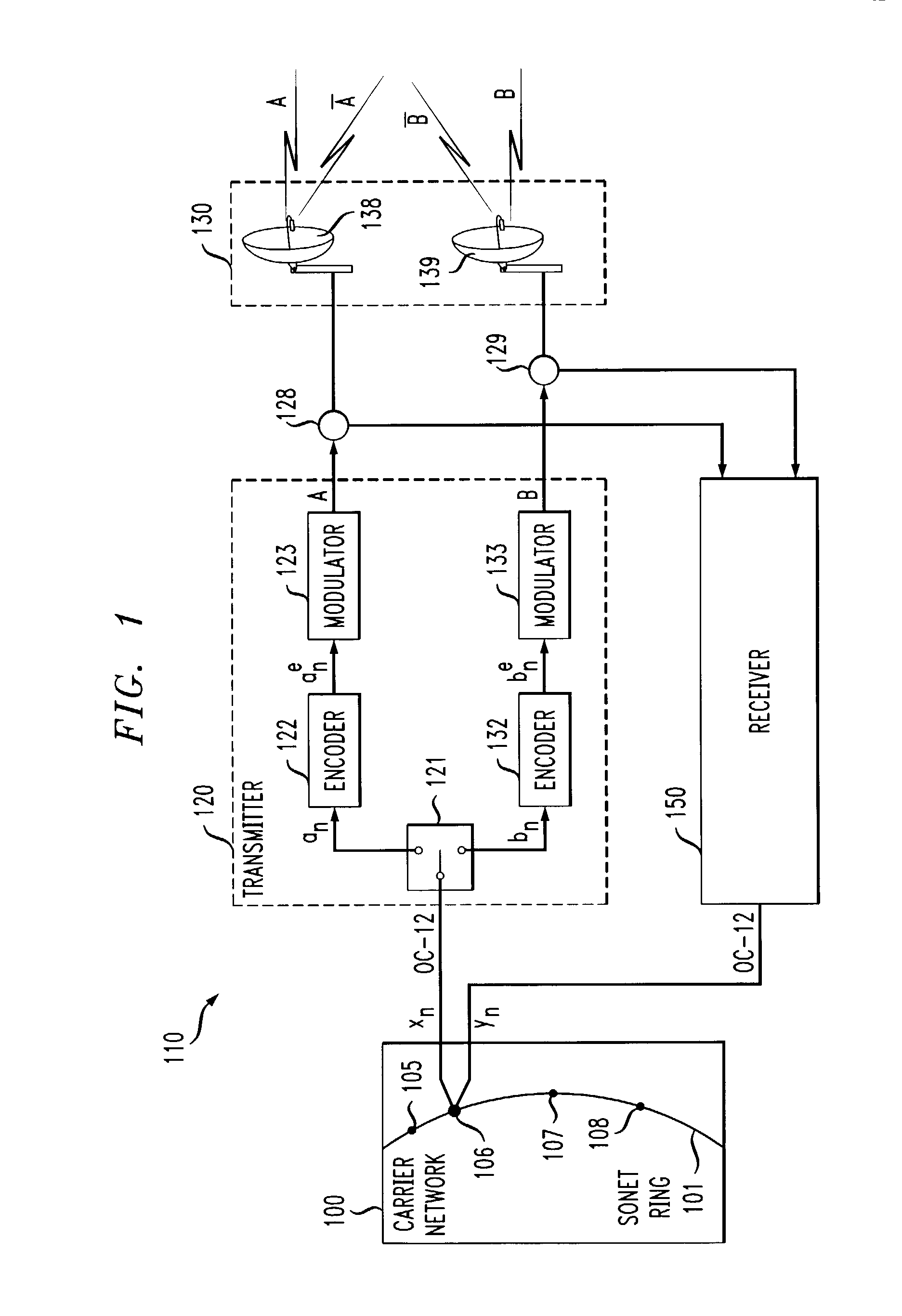
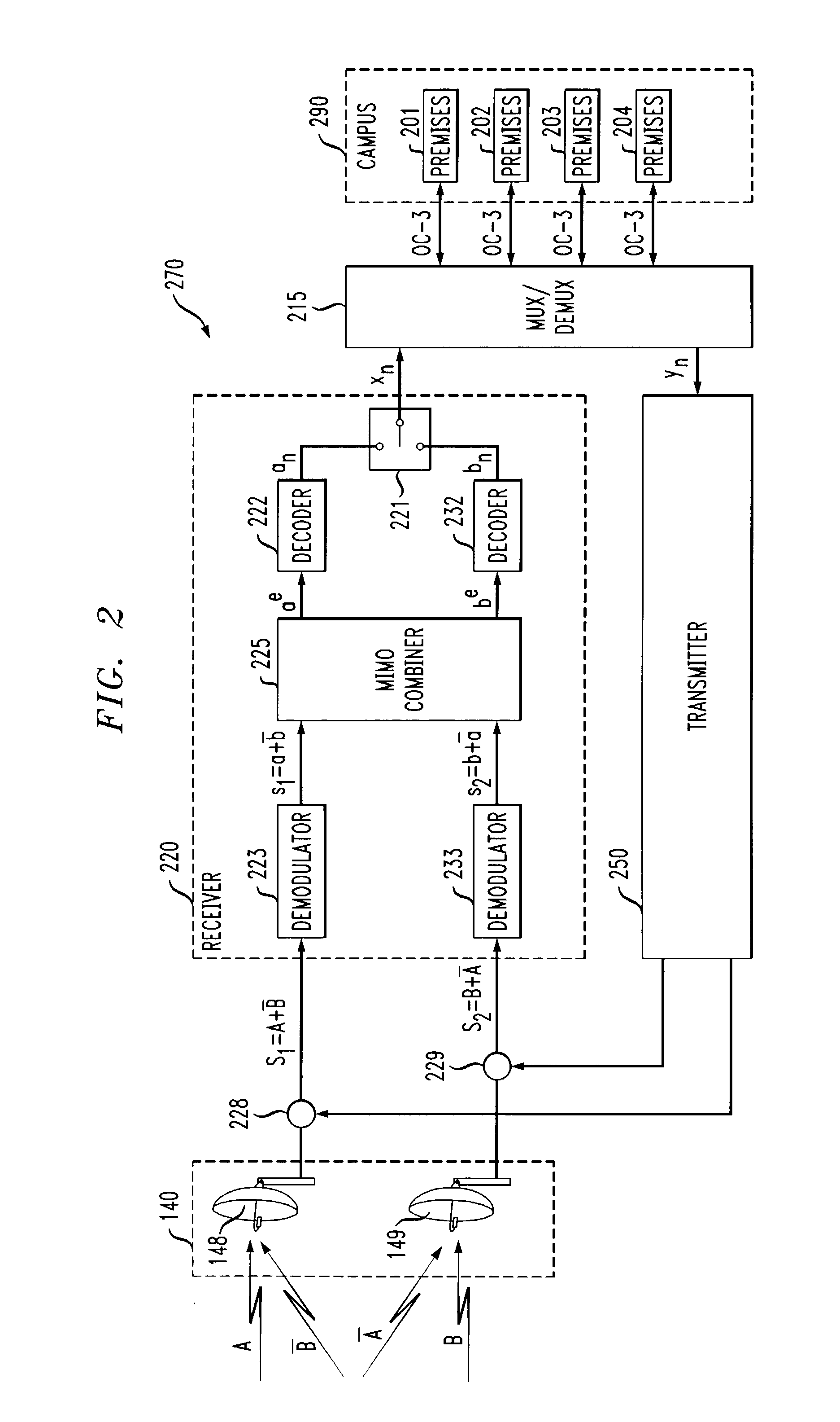
[0015]The arrangement shown in FIGS. 1–2 includes a service provider's carrier network 100 having optical communication paths and equipment including SONET ring 101. The latter has nodes 105 through 108. It is desired to communicate the bit stream contained within a 622 Mb / s OC-12 signal xn appearing at node 106 (hereinafter referred to as an OC-12 bit stream) to individual enterprise customer premises 201 through 204 which are in relatively close proximity to one another within, for example, a corporate campus 290 that is located at a distance from node 106—illustratively between about 1.5 to 8 kilometers. To this end, the 622 Mb / s OC-12 signal is applied to a transmitter 120 of a transceiver 110 installed in, for example, a utility room or in an outdoor enclosure near antenna system 130 described below. Within transmitter 120, a demultiplexer 121 divides the OC-12 bit stream xn into two bit, or data, streams an and bn. Bit stream an is channel-encoded by encoder 122. Encoder 122 i...


PUM


Abstract

Multiple-input / multiple-output (MIMO) antenna technology is used in a point-to-point radio link to provide higher data rates than would otherwise be achievable in a similar system that did not use MIMO antenna technology. Particular embodiments of the invention implement channel coding, dual polarization, adaptive receiver combining and adaptive power control.

Description

BACKGROUND OF THE INVENTION[0001]The present invention relates to methods and arrangements that provide digital communication links between fixed points.[0002]In order to extend a high-bandwidth / high-data-rate communication path from its main network out to the premises of, for example, an enterprise customer or a campus containing a number of enterprise customers, a telecommunications carrier will typically lay a fiber optic cable connecting the network to the customer premises. If terrain or other considerations preclude the use of fiber, an alternative is to set up a horn-antenna-based microwave link. However, data rates as high as the so-called OC-48 rate of 2.488 Gb / s, or even the Gigabit Ethernet / OC-12 rate of 622 Mb / s—which are often required in order to meet the needs of enterprise customers—are difficult to achieve using microwave links because bandwidths that such microwave links can support are limited and rain attenuation can be high at frequencies above 10 GHz.SUMMARY O...

Claims


Application Information

Patent Timeline
IPC IPC(8): H04B1/02H04B1/00H04B1/04H04B1/06H04B7/00
CPCH04W52/42H04B7/10
Inventor CLARK, MARTIN VIVIANDARCIE, THOMAS EDWARDGREENSTEIN, LAWRENCE JOELMARTIN, CAROL CATALANOWILLIS, III, THOMAS M.
Owner AMERICAN TELEPHONE & TELEGRAPH CO
Learn More