

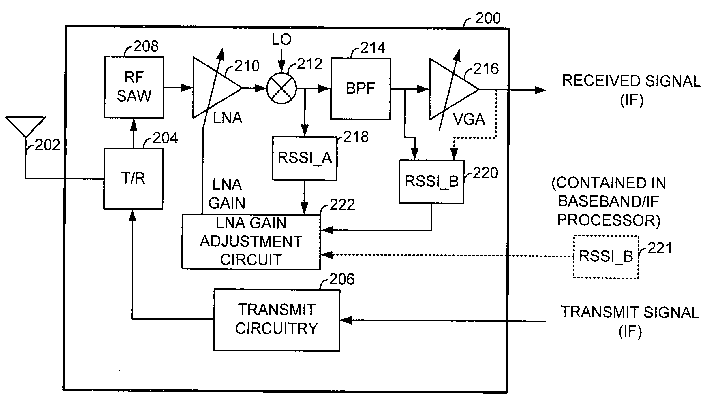
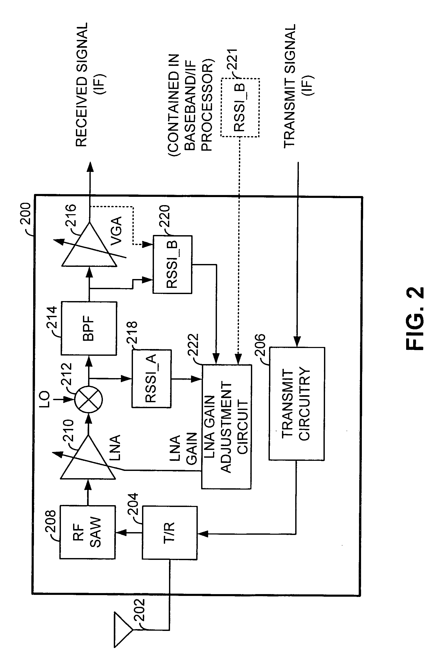
LNA gain adjustment in an RF receiver to compensate for intermodulation interference
a radio frequency (rf) receiver and gain adjustment technology, applied in the field of wireless communication, can solve the problems of reducing the snr of the signal produced by the mixer, reducing the gain of the lna, and the technique of setting the lna gain not working, so as to maximize the signal to noise ratio (snr) and maintain the linearity of the mixer
- Summary
- Abstract
- Description
- Claims
- Application Information
AI Technical Summary
Benefits of technology
Problems solved by technology
Method used
Image

Examples
Embodiment Construction
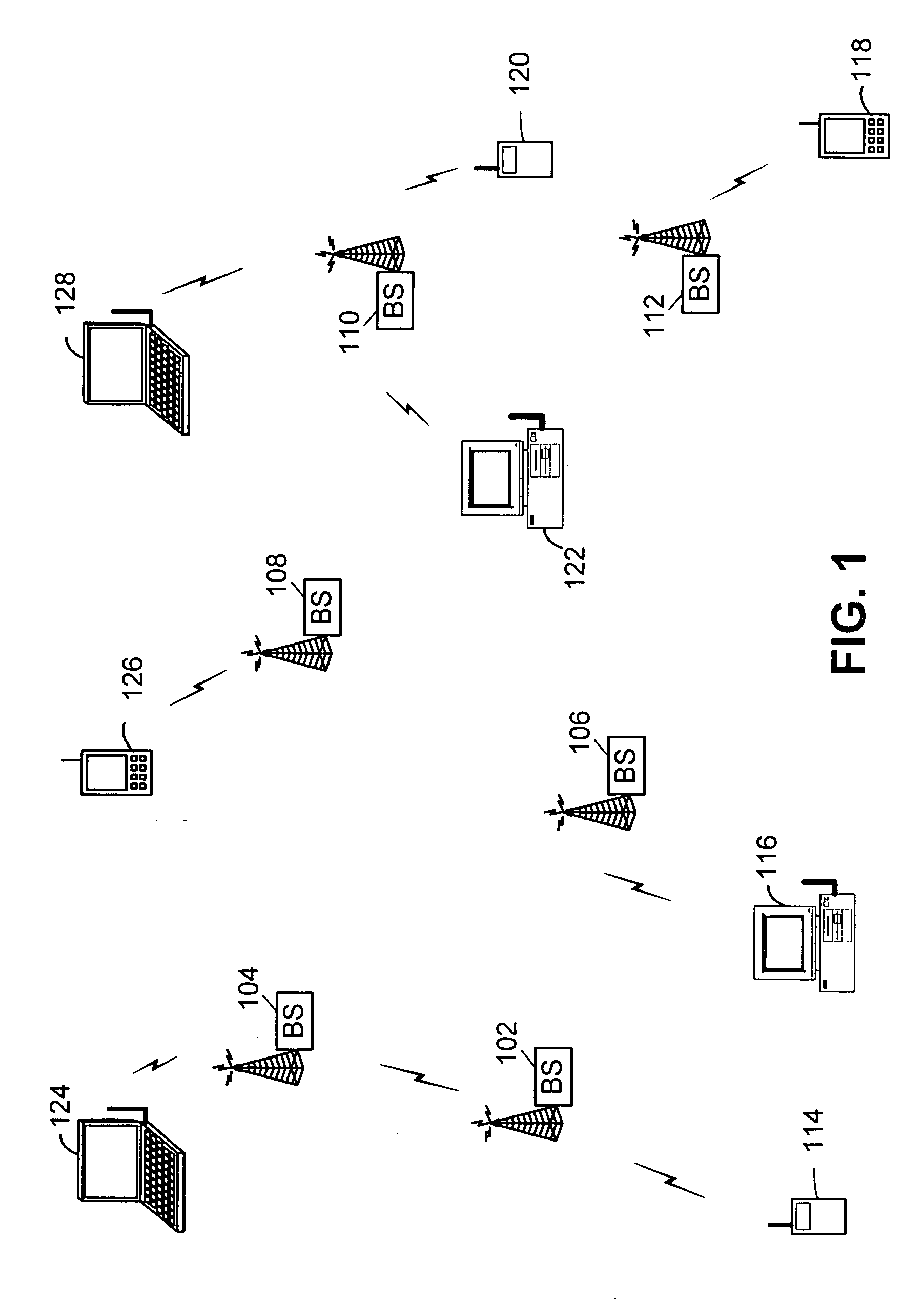
[0031]FIG. 1 is a system diagram illustrating a cellular system within which the present invention is deployed. The cellular system includes a plurality of base stations 102, 104, 106, 108, 110, and 112 that service wireless communications within respective cells / sectors. The cellular system services wireless communications for a plurality of wireless subscriber units. These wireless subscriber units include wireless handsets 114, 120, 118, and 126, mobile computers 124 and 128, and desktop computers 116 and 122. When wirelessly communicating, each of these subscriber units communicates with one (or more during handoff) of the base stations 102 through 112. Each of the subscriber units of FIG. 1, both subscriber units and base stations includes radio frequency circuitry.
[0032] The services provided by the cellular system include both voice service and data services. Such services are provided according to a cellular networking standard such as the GSM standards, the IS-136 standard...
PUM
 Abstract
Description
Claims
Application Information