
Iterative interference canceller for wireless multiple-access systems employing closed loop transmit diversity

Active Publication Date: 2007-05-17
III HLDG 1
View PDF12 Cites 24 Cited by
  • Summary
  • Abstract
  • Description
  • Claims
  • Application Information

AI Technical Summary

Benefits of technology

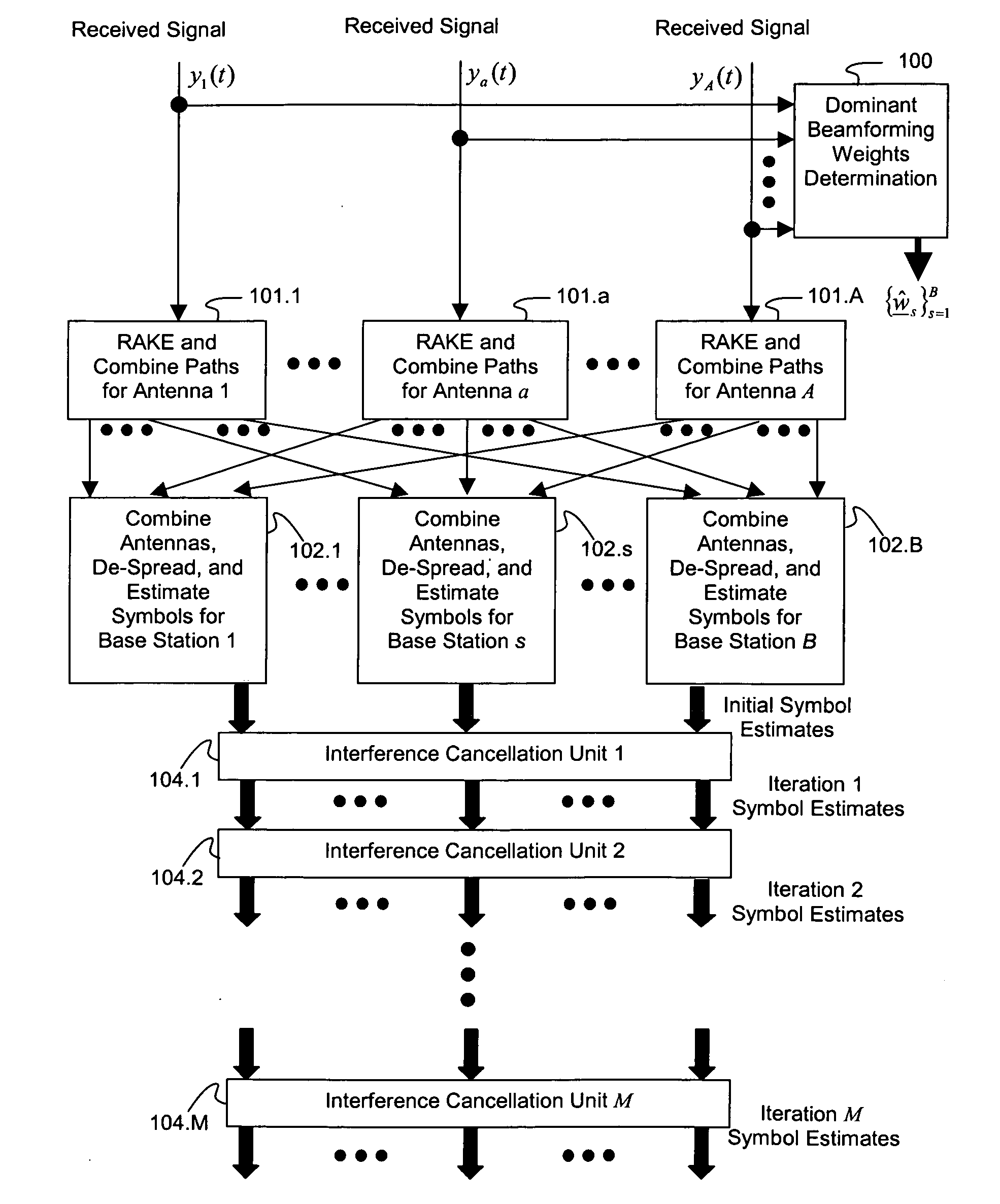
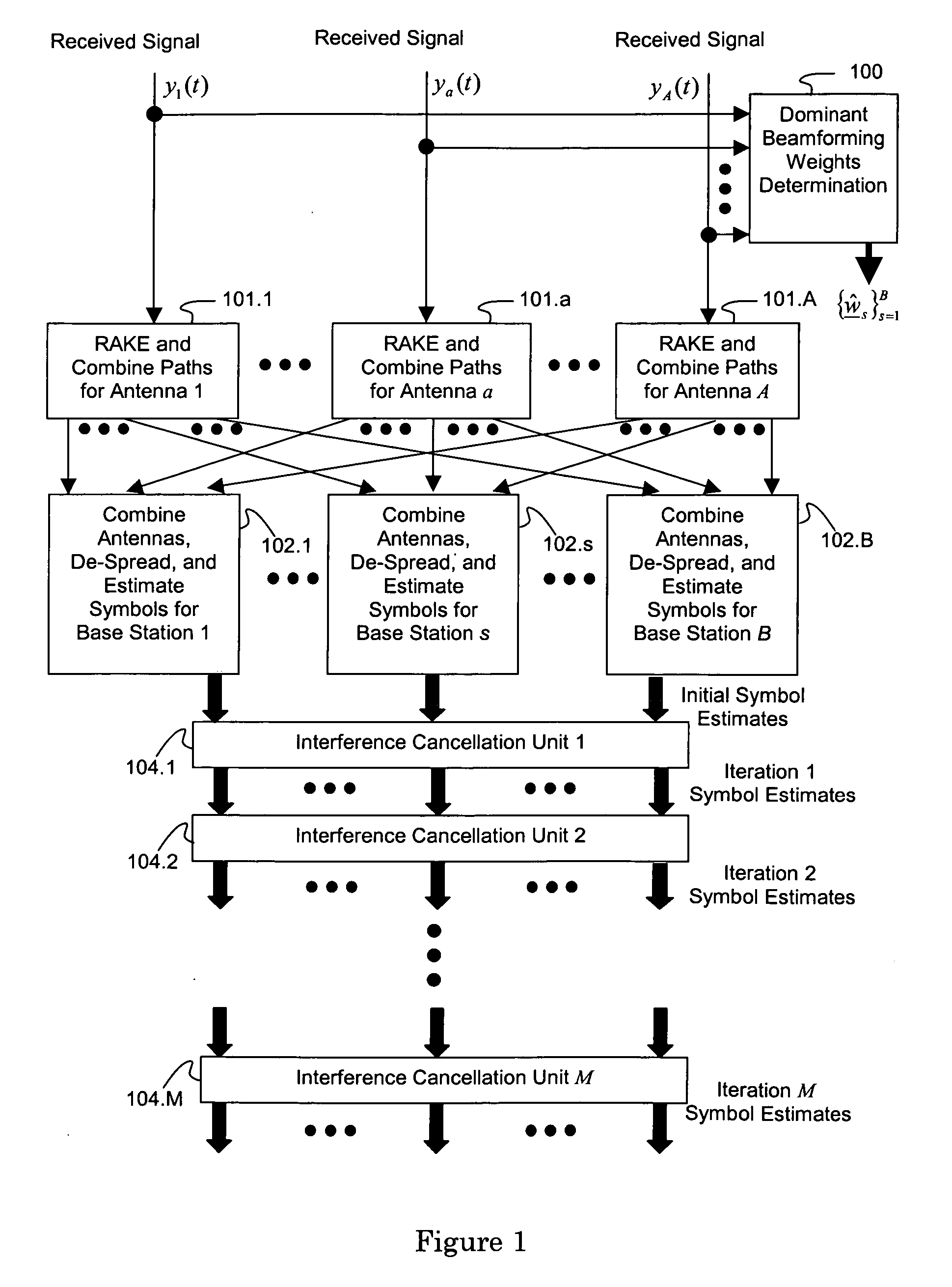
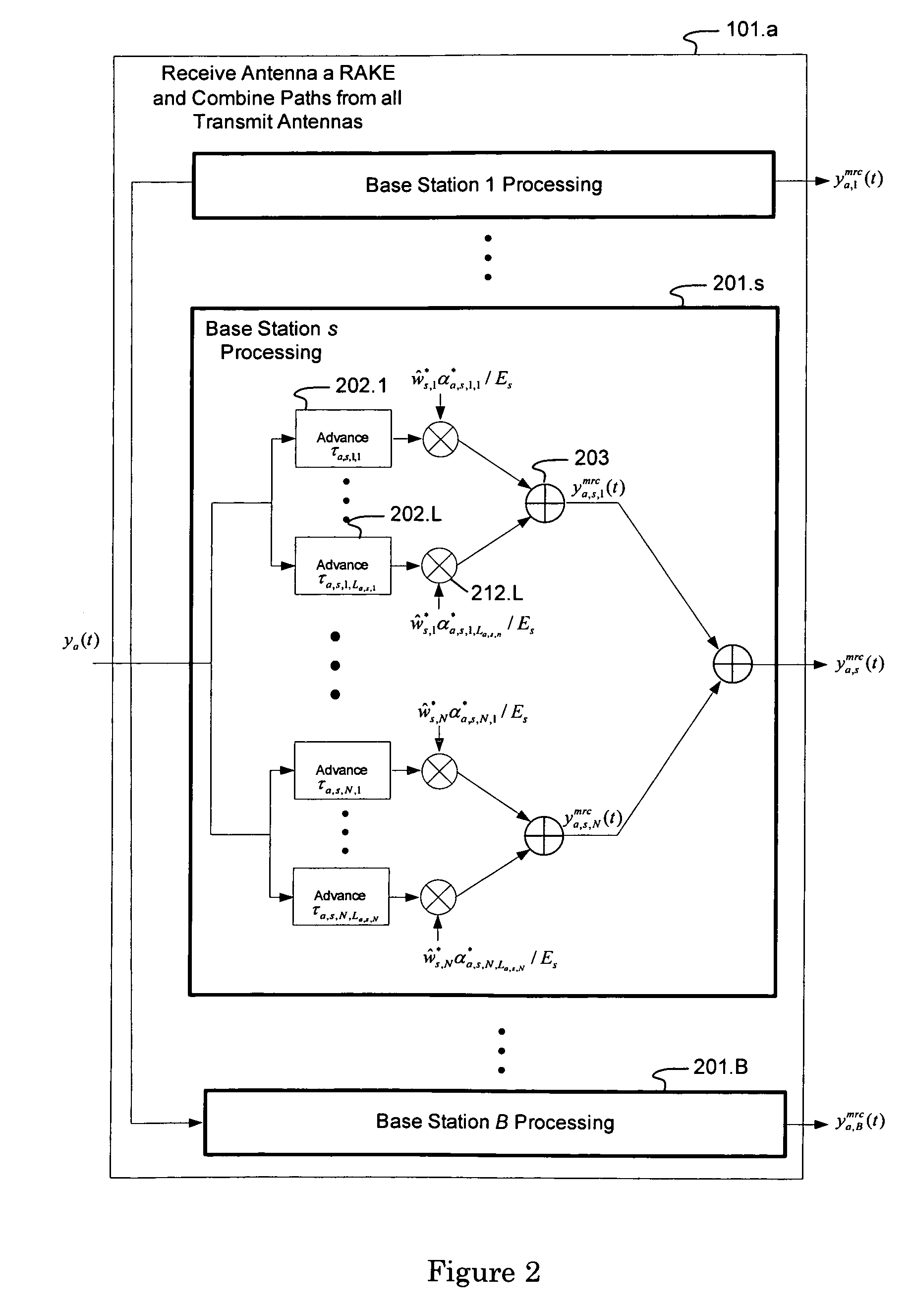
[0010] In view of the foregoing background, embodiments of the present invention may provide a generalized interference-canceling receiver for canceling intra-channel and / or inter-channel interference in multiple-access, coded-waveform transmissions that are formed by modulating the same information across a plurality of transmit antennas. Each associated transmit-antenna chain introduces a unique user-specific amplitude weight and phase shift to a user-specific waveform, with the purpose of maximizing the signal-to-noise ratio (or the total power) at each user-specific receiver. The transmitted signals propagate through a frequency-selective communication channel and are received by one or more receive antennas. Receiver embodiments may be designed, adapted, and implemented explicitly in software or programmed hardware, or implicitly in standard Rake-based hardware. Embodiments may be employed in user equipment on the downlink or in a base station on the uplink.

Problems solved by technology

Multipath can cause several types of interference.
Intra-channel interference occurs when the multipath time-spreading causes subchannels to leak into other subchannels.
When multiple base stations (or sectors or cells) are active, inter-channel interference may result from unwanted signals received from other base stations.
These types of interference can degrade communications by causing a receiver to incorrectly decode received transmissions, thus increasing a receiver's error floor.
Interference may degrade communications in other ways.
For example, interference may diminish the capacity of a communication system, decrease the region of coverage, and / or decrease maximum data rates.

Method used


Image

  • Iterative interference canceller for wireless multiple-access systems employing closed loop transmit diversity
  • Iterative interference canceller for wireless multiple-access systems employing closed loop transmit diversity
  • Iterative interference canceller for wireless multiple-access systems employing closed loop transmit diversity

Examples


Embodiment Construction

[0040] The present invention will now be described more fully hereinafter with reference to the accompanying drawings, in which preferred embodiments of the invention are shown. This invention may, however, be embodied in many different forms and should not be construed as limited to the embodiments set forth herein. Rather, these embodiments are provided so that this disclosure will be thorough and complete, and will fully convey the scope of the invention to those skilled in the art.

[0041] The following formula represents an analog baseband signal received by antenna a from multiple base stations employing CLTD when a single symbol is transmitted by each user on each symbol period (corresponding to vector-valued beam forming): ya⁡(t)=∑s=1B⁢ ⁢∑n=1N⁢ ⁢∑l=1La,s,n⁢ ⁢αa,s,n,l⁢∑k=1Ks⁢ ⁢ws,n,k⁢bs,k⁢us,k⁡(t-τa,s,n,l)+na⁡(t),t∈(0,T),Equation⁢ ⁢1

with the following definitions [0042] a represents the ath antenna of the mobile and ranges from 1 to A; [0043] (0,T) is the symbol interval; [0...


PUM


Abstract

An interference-canceling receiver processes coded, multiple-access, spread-spectrum transmissions that propagate through frequency-selective communication channels from multiple transmit antennas to multiple receive antennas in a closed-loop transmit-diversity channel. The receiver provides for repeated use of symbol-estimate weighting, subtractive cancellation with a stabilizing step-size, and mixed-decision symbol estimation. Receivers may be designed, adapted, and implemented explicitly in software or programmed hardware, or implicitly in standard Rake-based hardware, either within a Rake receiver at the finger level or outside the Rake at the user or subchannel symbol level. The receiver may be employed in user equipment on the forward link or in a base station on the reverse link.

Description

CROSS-REFERENCE TO RELATED APPLICATIONS [0001] This application claims priority to Provisional U.S. Pat. Appl. Ser. No. 60 / 736,204, filed Nov. 15, 2005, and entitled “Iterative Interference Cancellation Using Mixed Feedback Weights and Stabilizing Step Sizes,” and is a Continuation in Part of U.S. patent application Ser. No. 11 / 451,688, filed Jun. 13, 2006, and entitled “Iterative Interference Cancellation Using Mixed Feedback Weights and Stabilizing Step Sizes,” which are incorporated by reference in their entireties.BACKGROUND [0002] 1. Field of the Invention [0003] The present invention relates generally to cancellation of intra-channel and inter-channel interference in coded spread spectrum wireless communications systems having multiple transmit antennas and employing closed loop channel information fed back from a receiver to a transmitter. More specifically, the invention exploits spatial diversity afforded by multiple transmit and receive antennas, in combination with an int...

Claims


Application Information

Patent Timeline
IPC IPC(8): H04B1/00H04L1/02H04B1/707
CPCH04B1/7107H04B1/71072H04B1/71075H04B1/7115H04B7/0634H04L25/03006H04L2025/03375H04B1/00
Inventor GUESS, TOMMYMCCLOUD, MICHAEL L.
Owner III HLDG 1
Learn More