
Antenna system loaded in vehicle

a technology for a vehicle and an antenna system, which is applied in the direction of resonant antennas, differential interacting antenna combinations, substantially flat resonant elements, etc., can solve the problems of not being disclosed in detail, ensuring sufficient isolation, and affecting the service life of the ceramic substra

Active Publication Date: 2019-03-21
LG ELECTRONICS INC
View PDF6 Cites 39 Cited by
  • Summary
  • Abstract
  • Description
  • Claims
  • Application Information

AI Technical Summary

Benefits of technology

The invention provides communication services using multiple antennas on a vehicle antenna system structure. This allows for multiple communication services to be provided efficiently.

Problems solved by technology

However, there is a problem that a method of ensuring sufficient isolation between the LTE antennas while maintaining sizes mountable in the vehicle has not been disclosed in detail.
However, this patch antenna has a problem that the ceramic substrate may be damaged by an external impact and an antenna performance may be deteriorated accordingly.

Method used


Image

  • Antenna system loaded in vehicle
  • Antenna system loaded in vehicle
  • Antenna system loaded in vehicle

Examples


Embodiment Construction

[0048]Description will now be given in detail according to exemplary embodiments disclosed herein, with reference to the accompanying drawings. For the sake of brief description with reference to the drawings, the same or equivalent components may be provided with the same or similar reference numbers, and description thereof will not be repeated. In general, a suffix such as “module” and “unit” may be used to refer to elements or components. Use of such a suffix herein is merely intended to facilitate description of the specification, and the suffix itself is not intended to give any special meaning or function. In describing the present disclosure, if a detailed explanation for a related known function or construction is considered to unnecessarily divert the gist of the present disclosure, such explanation has been omitted but would be understood by those skilled in the art. The accompanying drawings are used to help easily understand the technical idea of the present disclosure ...


PUM


Abstract

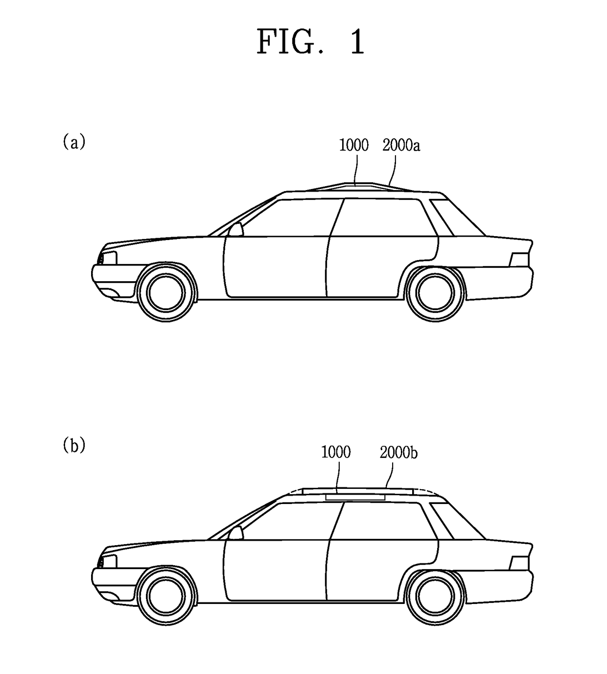
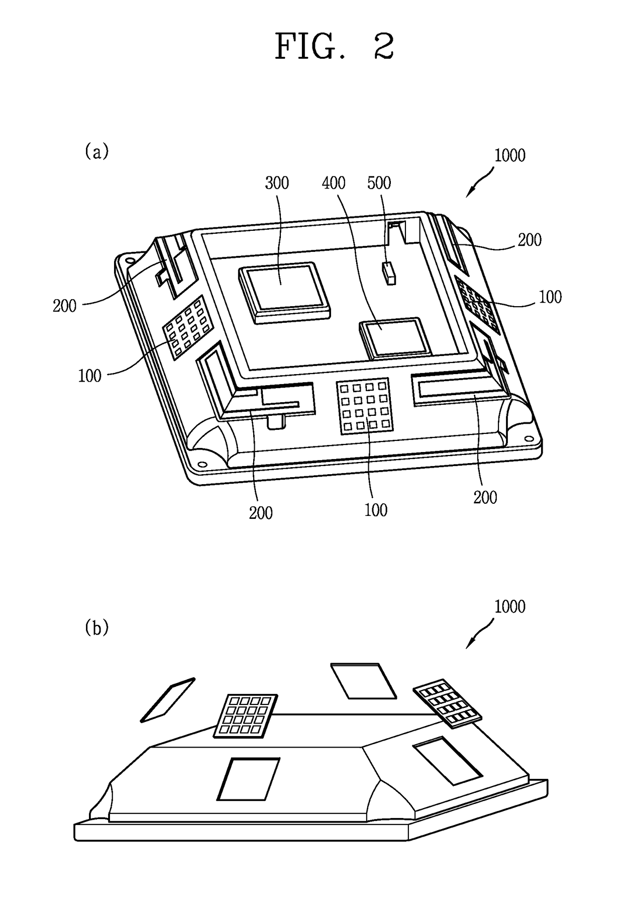
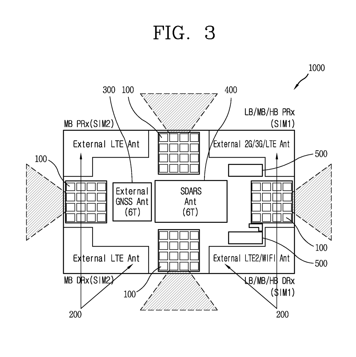
An antenna system loaded in a vehicle according to the present invention includes a first antenna system to perform beamforming by a plurality of first communication antenna elements disposed to transmit and receive a first signal according to a first communication system, and a second antenna system to perform a Multi Input Multi Output (MIMO) by a plurality of second communication antenna elements disposed to transmit and receive a second signal according to a second communication system, whereby a plurality of communication services can be provided through a flat vehicle antenna having beamforming array antennas capable of providing next generation communication services and MIMO antennas capable of providing existing mobile communication services.

Description

FIELD OF THE INVENTION[0001]The present invention relates to an antenna system loaded in a vehicle, and more particularly, to an antenna system mounted in a vehicle for providing communication services through transmission and reception of a plurality of communication signals.BACKGROUND OF THE INVENTION[0002]Terminals may be divided into mobile / portable devices and stationary devices according to mobility. Also, the mobile terminals may be classified into handheld types and vehicle mount types according to whether or not a user can directly carry.[0003]Functions of mobile terminals have been diversified. Examples of such functions include data and voice communications, capturing images and video via a camera, recording audio, playing music files via a speaker system, and displaying images and video on a display unit. Some mobile terminals include additional functionality which supports electronic game playing, while other terminals are configured as multimedia players. Specifically,...

Claims


Application Information

Patent Timeline
IPC IPC(8): H04B7/0404H01Q1/32H01Q21/29
CPCH04B7/0404H01Q1/325H01Q21/29H01Q25/04H04B7/0617H01Q1/002H01Q1/2283H01Q1/3275H01Q1/521H01Q9/0407H01Q21/065H01Q21/205H01Q21/28H01Q25/00H01Q1/32H01Q15/08
Inventor KIM, YONGKONPARK, JONGSUNJEONG, SUNIN
Owner LG ELECTRONICS INC
Learn More