

System comprising magnetically actuated motion control device
a motion control device and magnetic actuator technology, applied in the direction of shock absorbers, chairs, transportation and packaging, etc., can solve the problems of not being particularly easy to manufacture and assemble, and complicating manufacture and assembly
- Summary
- Abstract
- Description
- Claims
- Application Information
AI Technical Summary
Benefits of technology
Problems solved by technology
Method used
Image

Examples
first embodiment
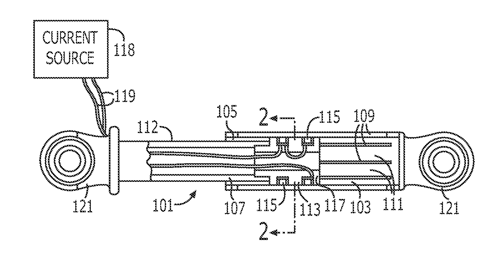
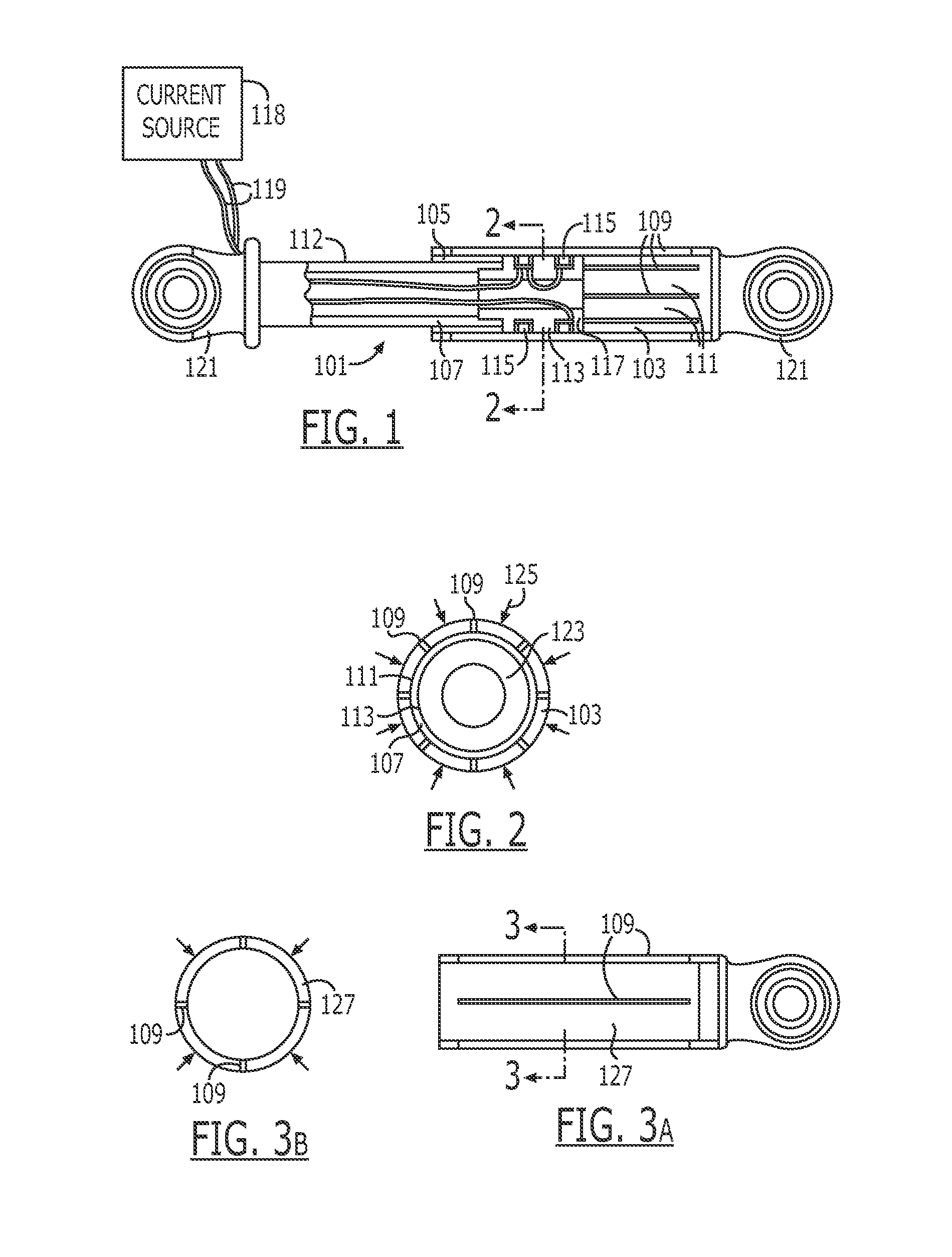
[0090]Turning to the drawings, a first exemplary embodiment of a magnetically actuated motion control device according to the present invention is shown in FIGS. 1 and 2. The first embodiment motion control device is a damper 101 and includes a housing 103 defining a cavity 105 in which a piston 107 is located. The housing 103 includes a least one longitudinal slot 109 (five of eight such slots can be seen in FIG. 1). The housing shown in FIG. 1 includes a plurality of slots that pass through the housing wall to define flexible bands, tabs, or fingers 111. The slots 109 extend through the wall of the housing 103 and extend nearly the entire length of the housing 103. Although narrow slots are illustrated in the Figures, it should be understood that a suitable wide slot could also be provided in the housing.
[0091]The piston 107 includes a shaft 112 having a magnetically active portion 113 made up of at least one, and preferably two electromagnetic coils 115 set in a magnetically perm...
second embodiment
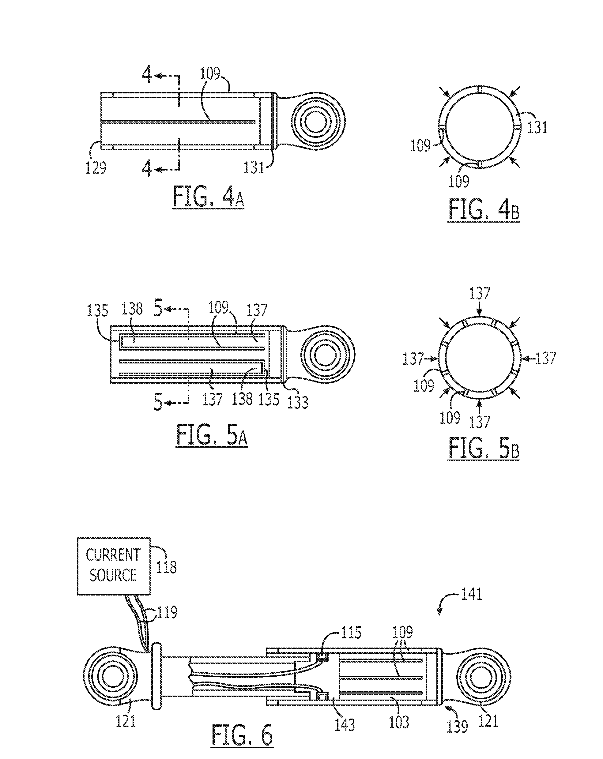
[0141]As explained earlier, the magnetic field generators, e.g., coils can be mounted to either the housing or the piston with the other of the housing or the piston being split into one or more flexible fingers. FIG. 41 shows a twenty-second embodiment of the present invention including a piston 413 having two magnetic coils 391 located within a core 414 and a slotted housing 415 in which the piston 413 is located. Like the embodiments discussed in reference to FIGS. 1 and 2, the housing 415 includes one or more longitudinal slots 417 that define one or more flexible fingers 419.
[0142]The piston 413 slides within the housing 415 on bearing assemblies 421, which are each located radially inward of the coils 391 and bear against the inner surface of the housing 415. Each bearing assembly includes an annular spring 425, which is located between an annular bearing 427 and one of the respective coils 391. The spring 425 biases the bearing 427 radially outward and away from the magnetica...
PUM
 Abstract
Description
Claims
Application Information