Case and stand for a portable computer

Inactive Publication Date: 2010-05-20
ANDREWS JOHN
View PDF7 Cites 124 Cited by
  • Summary
  • Abstract
  • Description
  • Claims
  • Application Information

AI Technical Summary

Benefits of technology

[0009]This provides an particular advantage that is not obtained from a stand or a protective case alone: the device is always useful to the user, and does not become an inconvenience, irrespective of whether the computer is being transported or is in use. Thus, it lacks the disincentives to use that are present in known stands and carrying cases. It also presents the computer to a user in an ergonomic disposition, raised from a supporting surface, that allows it to be used safely and comfortably.
[00

Problems solved by technology

Thus, it lacks the disincentives to use that a

Method used


Image

  • Case and stand for a portable computer
  • Case and stand for a portable computer
  • Case and stand for a portable computer

Examples


first embodiment

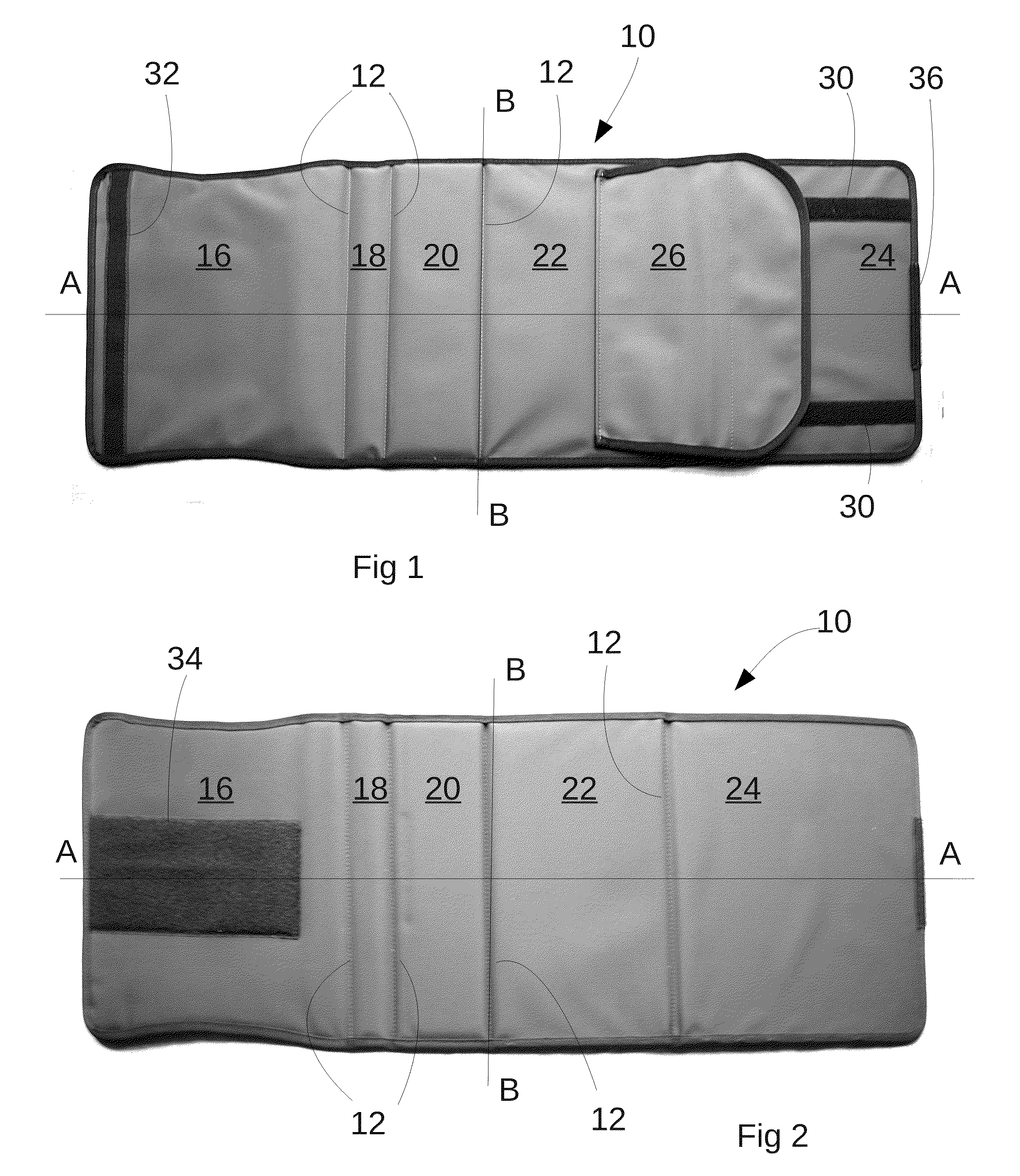
[0026]With reference to the drawings, a computer stand and transportation device being the invention comprises an approximately rectangular elongate sheet 10 of flexible material, in this case, a double layer of tough, woven nylon material with resilient padding, and, in some cases, stiffening material, between the layers. The sheet has a long axis A-A and a short axis B-B.

[0027]The sheet 10 is divided into several (in this embodiment, five) panels by lines of stitching 12 that extend across the sheet 10 through both of its layers parallel to the short axis B-B. Thus, the sheet 10 can be considered to comprise a plurality of panels interconnected by flexible strips at the lines of stitching that allow the panels to fold over one another. In this embodiment, the lines of stitching 12, and, therefore, the fold lines are parallel to one another. As shown in FIGS. 1 and 2, the panels will be identified, from left to right, as the first to the fifth panels, 16, 18, 20, 22, 24.

[0028]A cov...

fourth embodiment

[0048]the invention incorporates a modification to the support panel that can be applied to any of the embodiments described above. This will now be described with reference to FIGS. 13 to 16.

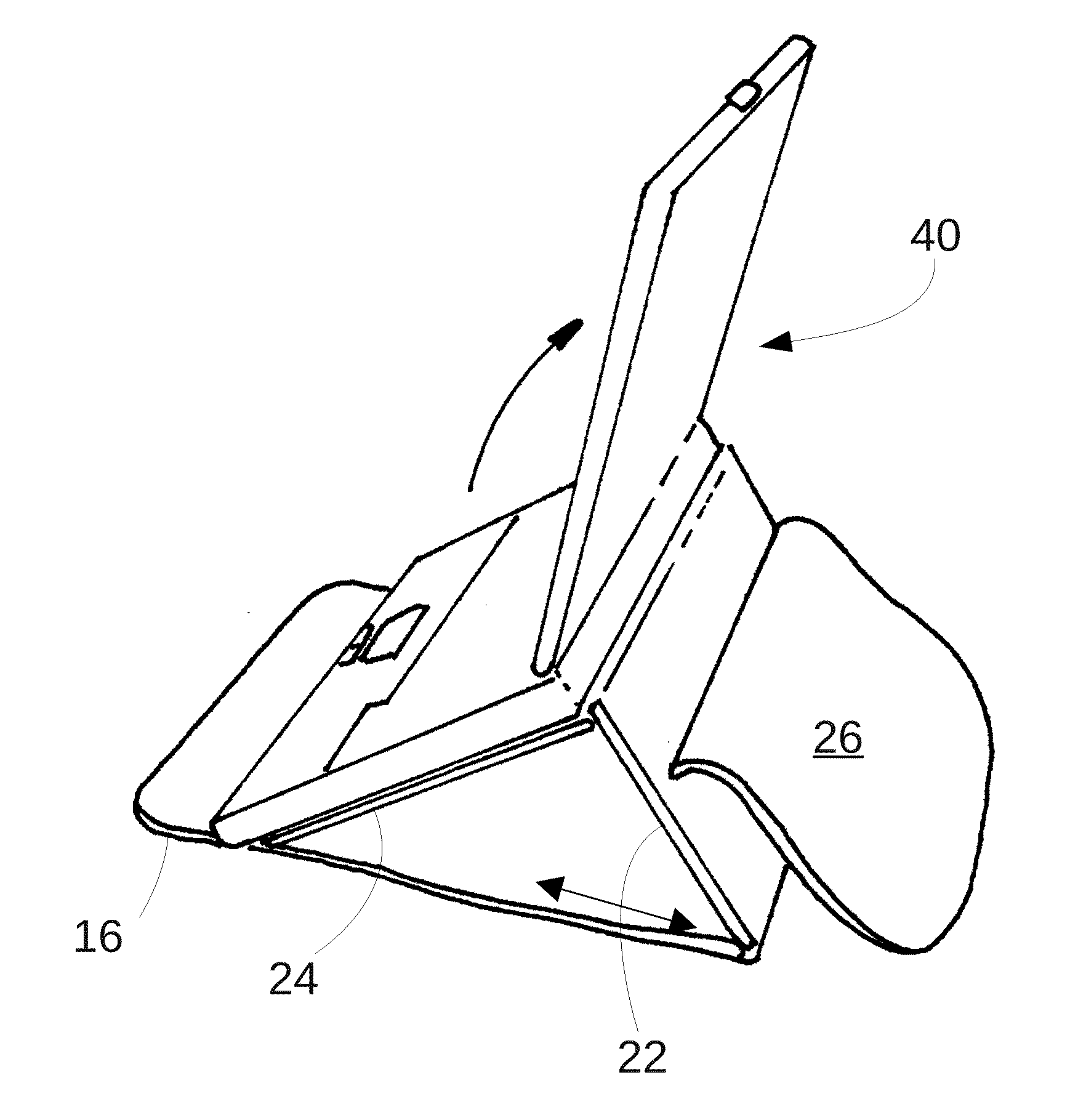
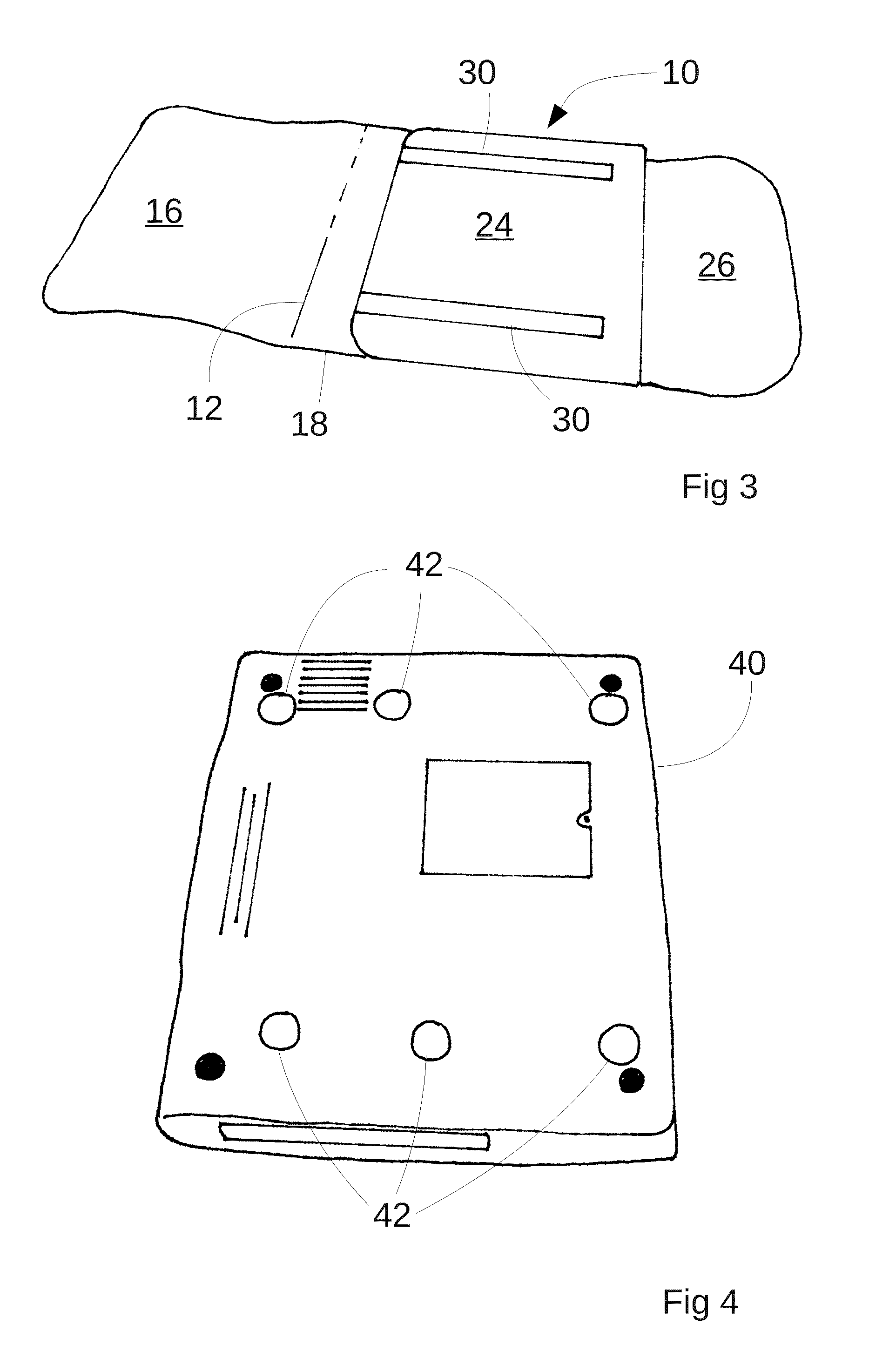
[0049]In this embodiment, the support panel 324 is in the form of a pouch with an opening indicated at 300. The pouch is formed of padded fabric material. As with previous embodiments, the support panel 324 has hook-and-loop fasteners on its supporting surface 330 that can optionally be used to secure a laptop 340 computer to it. A lower portion of the supporting panel 324 has a bulbous portion 302 that extends across the short axis of the case. As shown in FIG. 14, a computer 340 can be placed on the supporting surface, and it will be prevented from sliding off the stand by the bulbous portion 302.

[0050]For storage, the computer can be placed in the pouch where it is protected by the padded fabric. This leaves the supporting surface free for other uses, such as supporting papers or a book. Whe...


PUM


Abstract

A device that can be used as a case or a stand for a portable computer is disclosed. The device comprising a generally rectangular sheet having first to fifth interconnected panels (16, 18, 20, 22, 24) disposed along a long axis (A-A), the panels being interconnected by elements that allow them to fold with respect to one another about respective fold axes. The fifth panel has a support surface upon which a computer can be supported, the third and the forth panels are, together, in the direction of the long axis of approximately the same length as the fifth panel, and the first panel is of approximately the same dimension as the fifth panel. The first panel and the fifth panel carry fasteners (34, 36) such that a free edge region of the fifth panel can be connected to a face of the first panel. In a first configuration, the fifth panel is folded to overlie the third and the forth panels to the underside of a computer, the first panel is approximately parallel to the fifth panel, to the top of a computer, and the second panel extends approximately normally thereto to the front of a computer. In a second configuration, the edge region of the fifth panel is connected to the face of the first panel whereby the fifth panel, and a computer carried thereon, is supported on a slope by the fourth panel.

Description

BACKGROUND TO THE INVENTION[0001]1. Field of the Invention[0002]This invention relates to a case and stand for a portable computer.[0003]2. Summary of the Prior Art[0004]Portable computers (often known as “laptops” or “notebook computers”) are widely used by people who wish to be able to work or use their computers for leisure in a variety of places. This offers their users great convenience. Such computers are not without their disadvantages. A portable computer is a complex and expensive piece of equipment that can be damaged quite easily. Therefore, users of such computers must run the risk of damaging their machines, or transport them in a protective case. Some users find such a case inconvenient, because it adds to the bulk and weight of the computer, and the user must find somewhere to temporarily store the case when the computer is in use.[0005]Moreover, the compact nature of such computers imposes limitations upon the shape, size and configuration of their components, which ...

Claims


Application Information

Patent Timeline
IPC IPC(8): B65D85/00F16M11/02
CPCA45C3/02A45C9/00G06F1/1628A45C2013/025A45C2200/15A45C13/02
Inventor ANDREWS, JOHN
Owner ANDREWS JOHN
Why Eureka
Try Eureka