Assembling structure of radio IC tag
a radio ic tag and assembly technology, applied in the field can solve the problems of large difference in input and output impedance between radiation conductors (antennas), poor design, and inconvenient operation of radio ic tags
- Summary
- Abstract
- Description
- Claims
- Application Information
AI Technical Summary
Benefits of technology
Problems solved by technology
Method used
Image
Examples
first embodiment
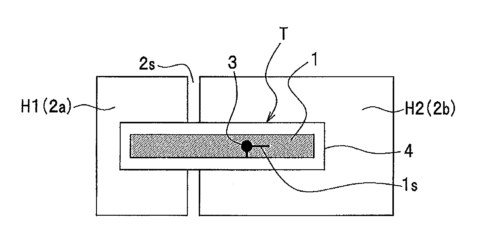
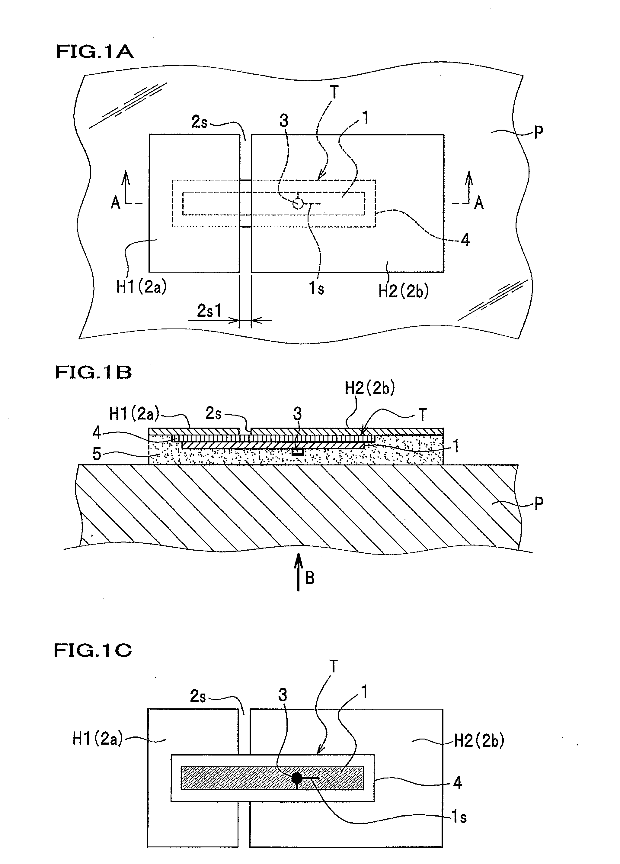
[0042]FIG. 1A is a top view illustrating a radio IC tag T according to a first embodiment of the present invention. In FIG. 1A, the radio IC tag T is arranged on a product P (indicated with dashed lines in FIG. 1B). FIG. 1B is a cross-sectional view when cut along the line A-A in FIG. 1A. FIG. 1C is a view in the direction of the arrow B in FIG. 1B.
[0043]The radio IC tag T according to the first embodiment is attached to a product P so as to discriminate the authentic from copies of the product P by reading information recorded in the radio IC tag T using a reader / writer (not shown).
[0044]The radio IC tag T illustrated in FIGS. 1A to 1C is equipped with an IC chip 3 on a side nearer to the product P, rather than to a hologram H (see FIG. 1B).
[0045]That is, the hologram H (which may collectively represent a hologram first part H1 and a hologram second part H2, and which may also be referred to as a second antenna to be described later) for enhancing decorative appearance and forgery ...
second embodiment
[0138]Next is described a second embodiment with reference to FIGS. 9A and 9B.
[0139]FIG. 9A is a view in the direction of the arrow B in FIG. 1B according to the second embodiment. FIG. 7B is a plan view illustrating a second antenna 42 of FIG. 9A.
[0140]The second embodiment is configured to have the second antenna 42, for example, in a substantial square shape when viewed from the top, because a hologram often used is in an elliptical shape.
[0141]Except the above-mentioned, a configuration of the second embodiment is similar to that of the first embodiment, and its detailed description is omitted herefrom.
[0142]As shown in FIG. 9B, in the second embodiment, the second antenna 42 has a substantially square shape as a whole and is divided into a substantially L-shaped second antenna first part 42a and a substantially square-shaped second antenna second part 42b via a slot 42s extending in a substantial L shape.
[0143]The substantially L-shaped second antenna first part 42a includes a ...
third embodiment
[0171]Next is described a third embodiment with reference to FIGS. 12A and 12B.
[0172]FIG. 12A is a view in the direction of the arrow B in FIG. 1B according to the third embodiment. FIG. 12B is a plan view illustrating a second antenna 72 of FIG. 12A.
[0173]The third embodiment has a configuration in which the second antenna first and second parts 2a, 2b, according to the first embodiment are unitarily formed.
[0174]Except the above-mentioned, the configuration of the third embodiment is similar to that of the first embodiment, and its detailed description is omitted herefrom.
[0175]As shown in FIG. 12A and FIG. 12B, the second antenna 72 according to the third embodiment includes a second antenna first area 72a, a second antenna second area 72b, and a second antenna third area 72c. The second antenna first area 72a and the second antenna second area 72b are disposed across a slot 72s. The second antenna third area 72c is an area which does not face the radio IC tag 7T. The second ante...
PUM
 Abstract
Description
Claims
Application Information
 - R&D
- Intellectual Property
- Life Sciences
- Materials
- Tech Scout
- Unparalleled Data Quality
- Higher Quality Content
- 60% Fewer Hallucinations
Browse by: Latest US Patents, China's latest patents, Technical Efficacy Thesaurus, Application Domain, Technology Topic, Popular Technical Reports.
© 2025 PatSnap. All rights reserved.Legal|Privacy policy|Modern Slavery Act Transparency Statement|Sitemap|About US| Contact US: help@patsnap.com


