
Wheelchair suspension system

Inactive Publication Date: 2010-05-20
CHELGREN ERIC MARK
View PDF15 Cites 14 Cited by
  • Summary
  • Abstract
  • Description
  • Claims
  • Application Information

AI Technical Summary

Benefits of technology

[0005]The present invention provides a rear suspension for a wheelchair which can be retrofitted to a wheelchair or installed at initial manufacture. The invention is directed toward a manually operated wheelchair, especially a sport wheelchair, which is driven by the rider pushing the large rear wheels by hand. The present invention provides a shock absorbing apparatus which isolates the large rear wheels from the wheelchair frame to reduce the shock and vibration felt by the user of a wheelchair traversing a surface.
[0007]The rear suspension may flex vertically while the axle support plates remain in a substantially vertical orientation throughout such flexure. As a result, camber angle of the rear wheels retained to the suspension member does not change because of vertical flexure of the suspension.
[0009]An upper plate is centered atop the upper leaf spring and a lower plate is centered below and touching the lower leaf spring. The upper plate and lower plate are best composed of aluminum so that the weight of the suspension remains minimal. Voids in the upper plate and lower plate serve to lessen the weight of the plates. The upper and lower plates retain the upper and lower leaf springs to the mounting elements by plural bolts passing from upper plate through to the lower plate.
[0010]It is an object of the invention to provide a shock absorbing apparatus to reduce the transmission of bumps and shocks from the large rear wheels of a wheelchair to the rider in the wheelchair.
[0011]It is a further object of the invention to provide an improved manual wheelchair which is less uncomfortable for the user to ride over irregular surfaces.
[0012]It is also an object of the invention to provide a shock absorbing rear suspension which can be easily added to an existing wheelchair.

Problems solved by technology

These shocks and vibrations contribute to spasms and back pain in wheelchair users.
Studies have shown that low back pain is a common problem among people with disabilities who use wheelchairs.

Method used


Image

  • Wheelchair suspension system
  • Wheelchair suspension system
  • Wheelchair suspension system

Examples


Embodiment Construction

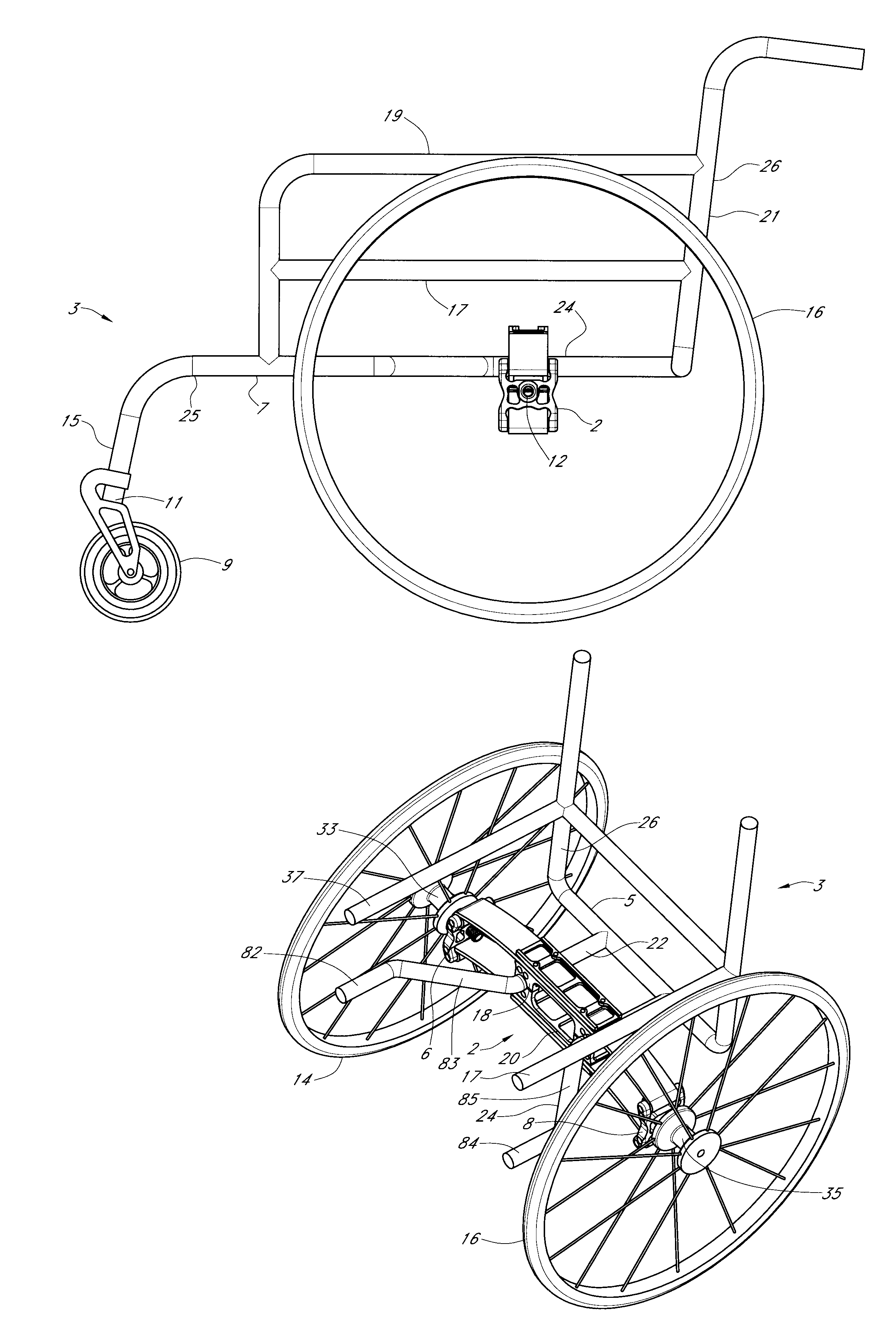
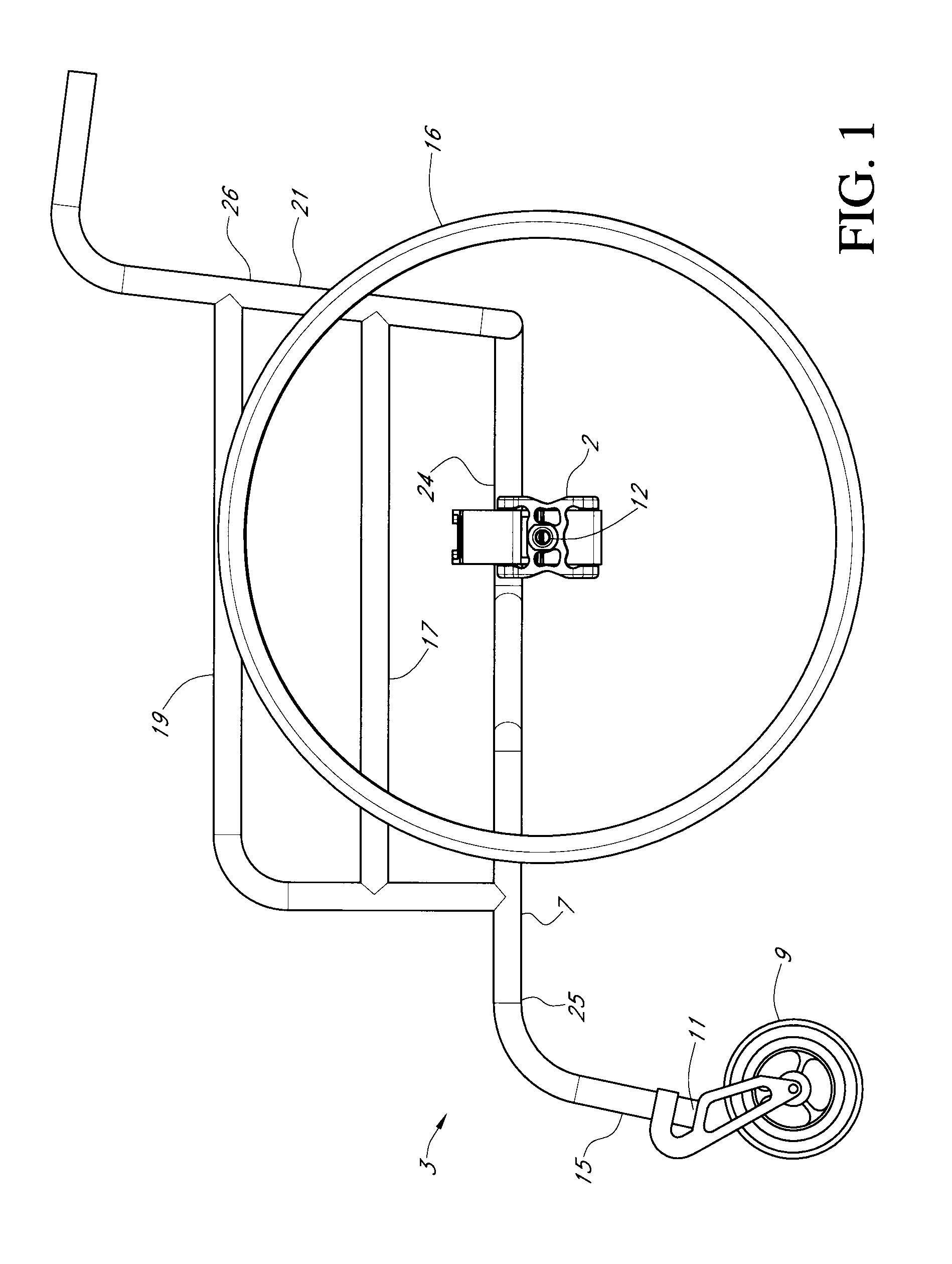
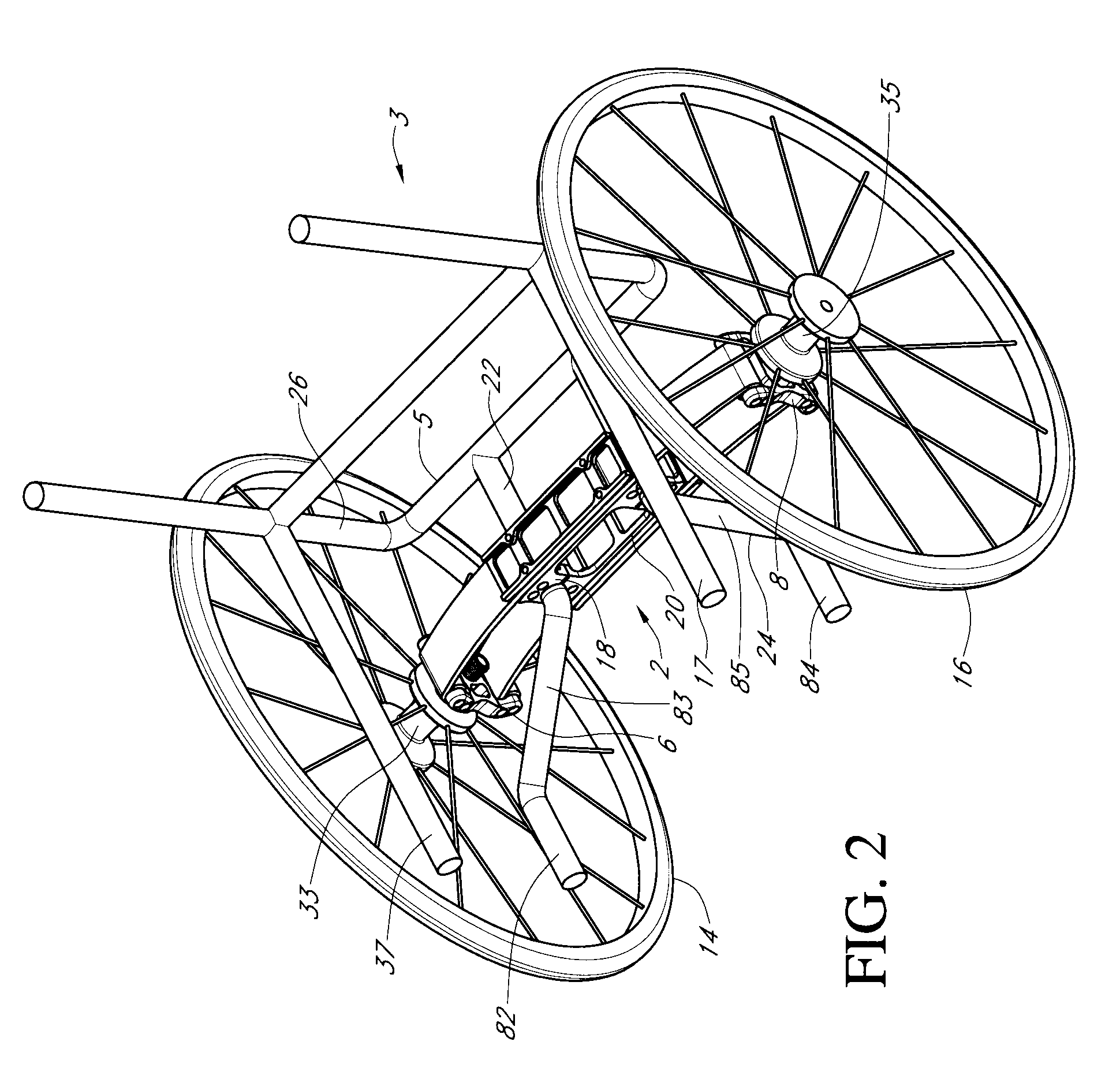
[0021]FIG. 1 discloses a wheelchair 3 which comprises large rear wheels of which left side rear wheel 16 is seen in this figure. The wheelchair frame 7 is supported on the rear wheels and by front casters, of which caster 9 on left side of wheelchair 3 can be observed in FIG. 1. Caster 9 is connected to lower end 11 of front frame element 15 which is oriented generally vertically. Front frame element 15 is joined to wheelchair frame 7 at front end 25 thereof. All parts of wheelchair frame 7 are preferably tubular and of light weight metals. Wheelchair frame 7 includes rear frame assembly 26 which comprises lower longitudinal elongate tubular member 24 as well as intermediate side bar 17 and upper side bar 19, all of which extend longitudinally forward of upright rear frame element 21. Mirror images of lower tubular member 24, intermediate side bar 17 and upper side bar 19 are provided on the opposing side of wheelchair frame 7 as will be seen in FIGS. 2, 3. A seat cushion and seat c...


PUM


Abstract

A wheelchair suspension system includes a suspension member which clamps to longitudinal bars of the wheelchair frame located below the seat of the wheelchair. The suspension member is elongate with upper and lower parallel leaf springs extending between the opposing ends of the suspension member. An axle support member is hinged to each end of the suspension member, by pivotal connection to each of the leaf springs. Each axle support member receives the axle of one of the opposing large rear wheels of the wheelchair. As the large wheels encounter uneven areas on the ground surface on which the wheelchair moves, the leaf springs flex reducing vibrations and shock to the wheelchair occupant. The axle support members maintain their generally upright orientation as the leaf springs flex so that camber angle of the rear wheels does not change.

Description

CROSS-REFERENCE TO RELATED APPLICATIONS[0001]This application claims priority from copending provisional patent application entitled WHEELCHAIR SUSPENSION SYSTEM, Ser. No. 61 / 115,364 filed Nov. 17, 2008. The disclosure of provisional patent application Ser. No. 61 / 115,364 is hereby incorporated in its entirety.BACKGROUND OF THE INVENTION[0002]The present invention pertains to wheelchairs and particularly to suspension of the large rear wheels of wheelchairs which are manually operable.[0003]In the typical manual wheelchair each rear wheel is a large wheel mounted to the frame of the wheelchair without any provision for absorption of shocks or damping of vibration of the wheelchair. In such a wheelchair, shocks and vibrations arising from irregularities and defects in the traveled surface are transmitted through the rear wheels to the wheelchair occupant. These shocks and vibrations contribute to spasms and back pain in wheelchair users. Studies have shown that low back pain is a com...

Claims


Application Information

Patent Timeline
IPC IPC(8): B60G9/00B62M1/14
CPCA61G5/10A61G2005/1078B60G2300/024B60G11/08A61G2005/1097A61G5/1078A61G5/1097
Inventor CHELGREN, ERIC MARK
Owner CHELGREN ERIC MARK
Learn More