Tapered helical auger turbine to convert hydrokinetic energy into electrical energy

a technology of hydrokinetic energy and tapered helical augers, which is applied in the direction of machines/engines, liquid fuel engines, electric generator control, etc., can solve the problems of ineffective storage devices, high cost, and often only being able to operate systems, and achieves the effect of increasing the percentage of moving fluid energy

Active Publication Date: 2010-05-20
ANDERSON JR WINFIELD SCOTT
View PDF28 Cites 41 Cited by
  • Summary
  • Abstract
  • Description
  • Claims
  • Application Information

AI Technical Summary

Problems solved by technology

However, such systems were often only able to operate when the water was flowing in one direction.
Even if energy could be generated from a tidal flow in both directions of flow, other significant issues arise because peak power flow is only available from a tidal flow at roughly 12-hour intervals.
This can cause issues with maximum grid capacities needed to transmit the generated power.
Storage devices to smooth out dispatch of power are desirable, but land requirements for the huge batteries, dual reservoir requirements for hydro storage and low efficiency of fuel cells have made known storage devices too expensive to be effective.
Thus, known hydrokinetic devices have not been economically viable.
Significant issues are also caused by known devices to marine life, which can be harmed by the rotating turbine blades.
However, the cages do nothing to prevent smaller fish from being harmed.
Additionally, many proposed turbine blades can suffer damage from water-borne debris, and even shipping.
Due to these problems, acceptance of hydrokinetic devices by local communities and environmentally aware groups has not been as strong as hoped for, and the reliability of the devices has been limited.
This can be prohibitively expensive, as it can involve anchoring installations, and also the installation of energy supply cabling and pipes.
Additionally, once installed, there is typically not much flexibility to allow the turbines to move with different water flows.
For the foregoing reasons, none of the suggested hydrokinetic energy devices have been successful in practice.
This can prolong the useful life of oil platforms even after drilling is no longer economically feasible.

Method used


Image

  • Tapered helical auger turbine to convert hydrokinetic energy into electrical energy
  • Tapered helical auger turbine to convert hydrokinetic energy into electrical energy
  • Tapered helical auger turbine to convert hydrokinetic energy into electrical energy

Examples


Embodiment Construction

[0026]The exemplary embodiments of the present disclosure are described with respect to a helical auger turbine that can be used in a hydrokinetic energy converter, specifically one that can be used in a tidal flow or river flow. It should be understood by one of ordinary skill in the art that the exemplary embodiments of the present disclosure can be applied to other types of hydrokinetic devices and generators, and even to wind generators.

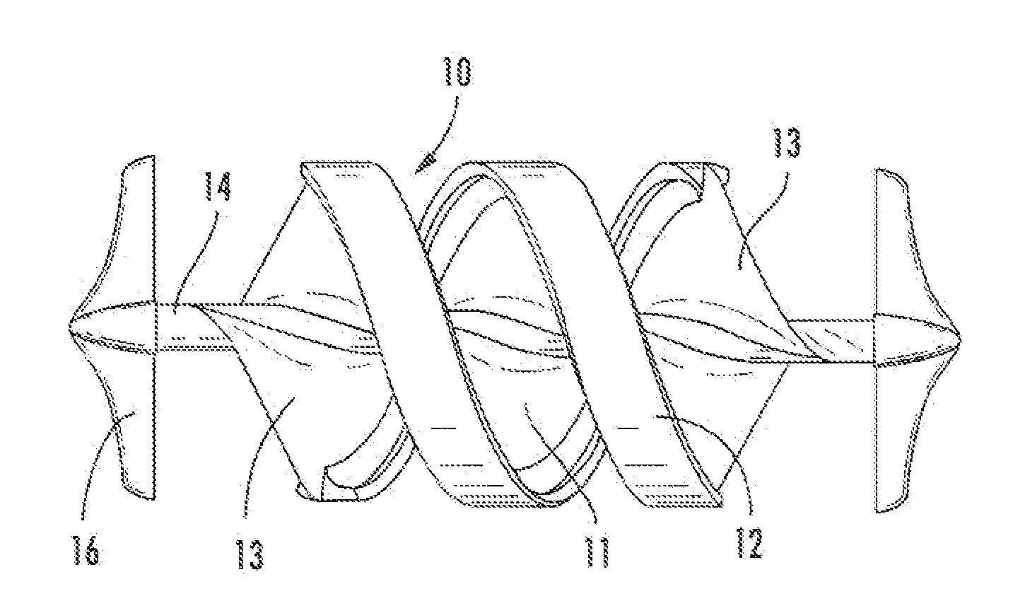
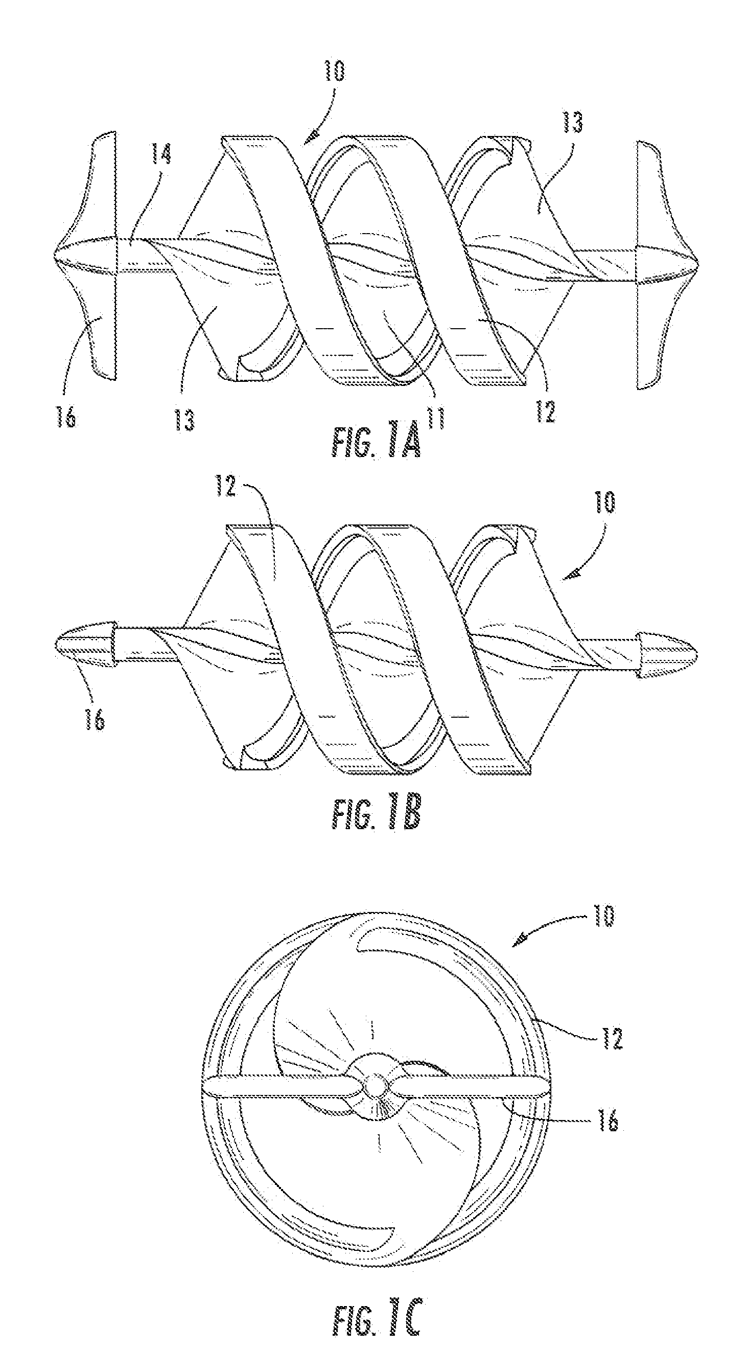
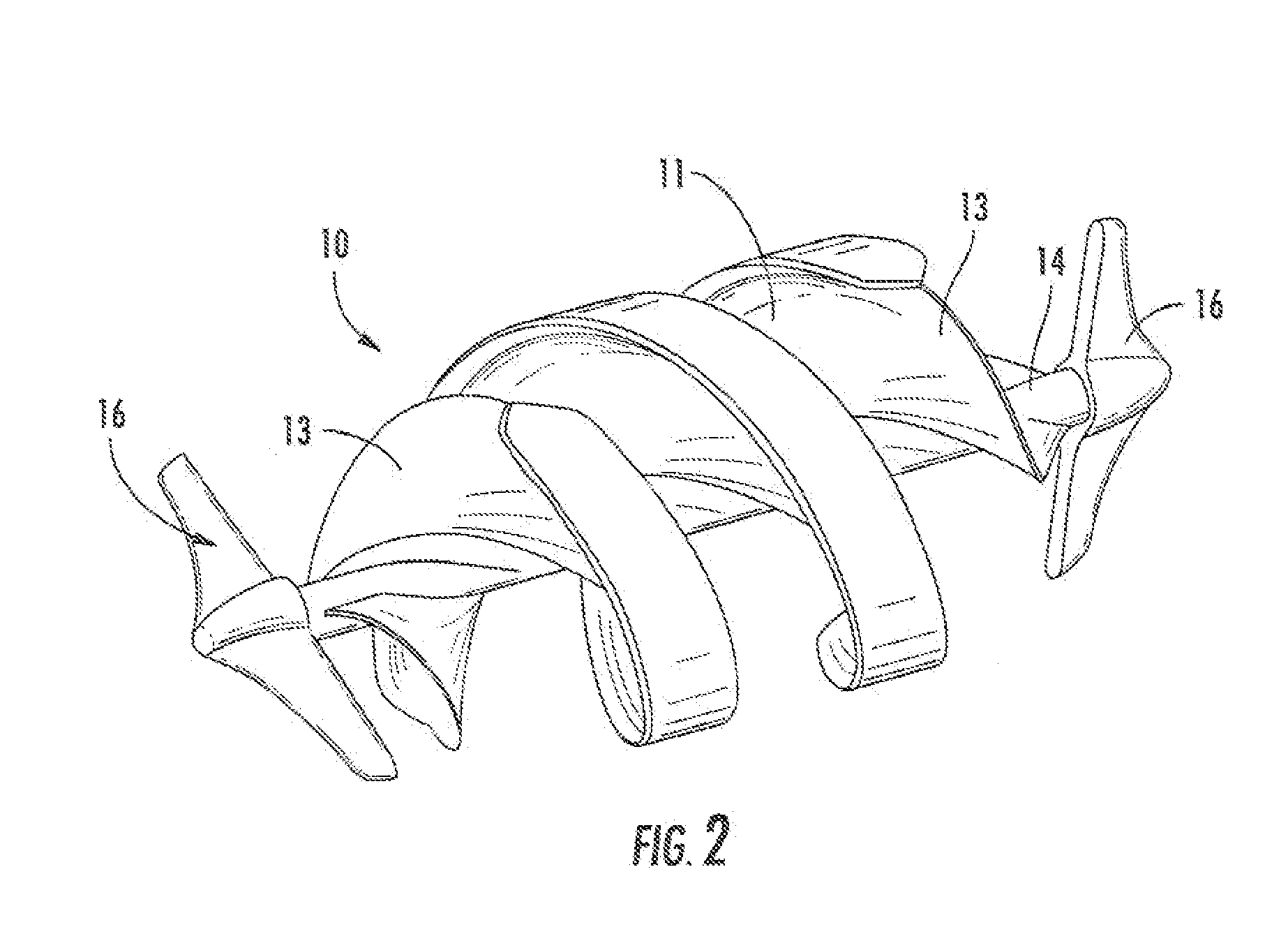
[0027]Referring to the drawings, an exemplary auger turbine 10 is shown. The auger 10 is preferably formed of a lightweight material, such as rotationally molded plastics or molded carbon fiber. It will be appreciated that any suitable material may be used. Reinforcing structures, such as metal ribbing, may be included internally in the turbine blade. In order to aid buoyancy, the auger may be hollow, or can include air pockets or other buoyancy aids. In a preferred arrangement, the helical auger turbine 10 comprises a helical turbine blade 11 pr...


PUM


Abstract

A helical auger turbine and hydrokinetic device for use with electrical generators for producing electricity. The auger turbine includes a generally helical turbine blade rotatably mounted on a central shaft, which may be tapered at each end, and a flange extending perpendicularly to an edge of the turbine blade. At least one turbine blade support connection is included for connecting the central shaft to a support structure. An electrical generator may be powered by the helical auger turbine, that can be used in a tidal water flow. The helical auger turbine can operate a high pressure pump connected to a hydraulic accumulator for storing pressurized hydraulic fluid from the high pressure pump. An electrical generator can be operated by hydraulic fluid delivered from the hydraulic accumulator at times of slow water flow. A plurality of helical auger turbines can be horizontally oriented under water, tethered to legs of an ocean platform such as an oil rig secured to the seabed.

Description

CROSS-REFERENCE TO RELATED APPLICATION[0001]This patent application claims the benefit of U.S. Provisional Patent Application No. 61 / 116,540, filed Nov. 20, 2008, the entirety of which is incorporated by reference.FIELD OF THE INVENTION [0002]The present application relates to a hydrokinetic energy converter, and particularly to a tapered helical auger turbine that can be coupled by hydraulic circuits to a generator to produce electricity from flowing water.BACKGROUND[0003]Many proposals have been made for generating electricity from tidal and other water flows, using hydrokinetic energy generation. A Policy Statement issued on Nov. 30, 2007 by the Federal Energy Regulatory Commission stated that “[e]stimates suggest that new hydrokinetic technologies, if fully developed, could double the amount of hydropower production in the United States, bringing it from just under 10 percent to close to 20 percent of the national electric energy supply. Given the potential benefits of this new,...

Claims


Application Information

Patent Timeline
Patent Type & Authority Applications(United States)
IPC IPC(8): F03B13/26F04D3/02
CPCF03B13/264F03B17/061F05B2240/40F05B2240/97Y02E10/38F05B2250/292Y02E10/28Y02E10/725F05B2250/25Y02E10/30Y02E10/72Y02E10/20
Inventor ANDERSON, JR., WINFIELD SCOTT
Owner ANDERSON JR WINFIELD SCOTT
Why Eureka
Try Eureka