Non-contact power transfer apparatus

Active Publication Date: 2010-05-20
MURATA MFG CO LTD
View PDF9 Cites 41 Cited by
  • Summary
  • Abstract
  • Description
  • Claims
  • Application Information

AI Technical Summary

Benefits of technology

[0009]The present invention has been made in view of the foregoing problems, and has an object to provide a non-contact power transfer apparatus which i

Problems solved by technology

Hence, when the metal piece is attached about to the power transmission coil, the metal piece generates heat dangerously.
Besides, when the metal piece is placed on the power transmission unit, there may occur displacement of the power transmission coil from the power reception coil so that there arise problems that charge efficiency is deteriorated and charge time becomes longer.
Further,

Method used


Image

  • Non-contact power transfer apparatus
  • Non-contact power transfer apparatus
  • Non-contact power transfer apparatus

Examples


Embodiment Construction

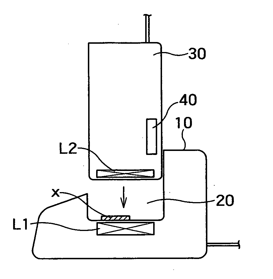
[0019]According to the non-contact power transfer apparatus of the present invention, when a metal piece such a coin is attached to the support base of the power transmission unit main body, or when the power reception unit is not mounted on the support base properly, the unit detection means provided on the power transmission unit is used to prevent power transfer from the power transmission coil to the power reception coil.

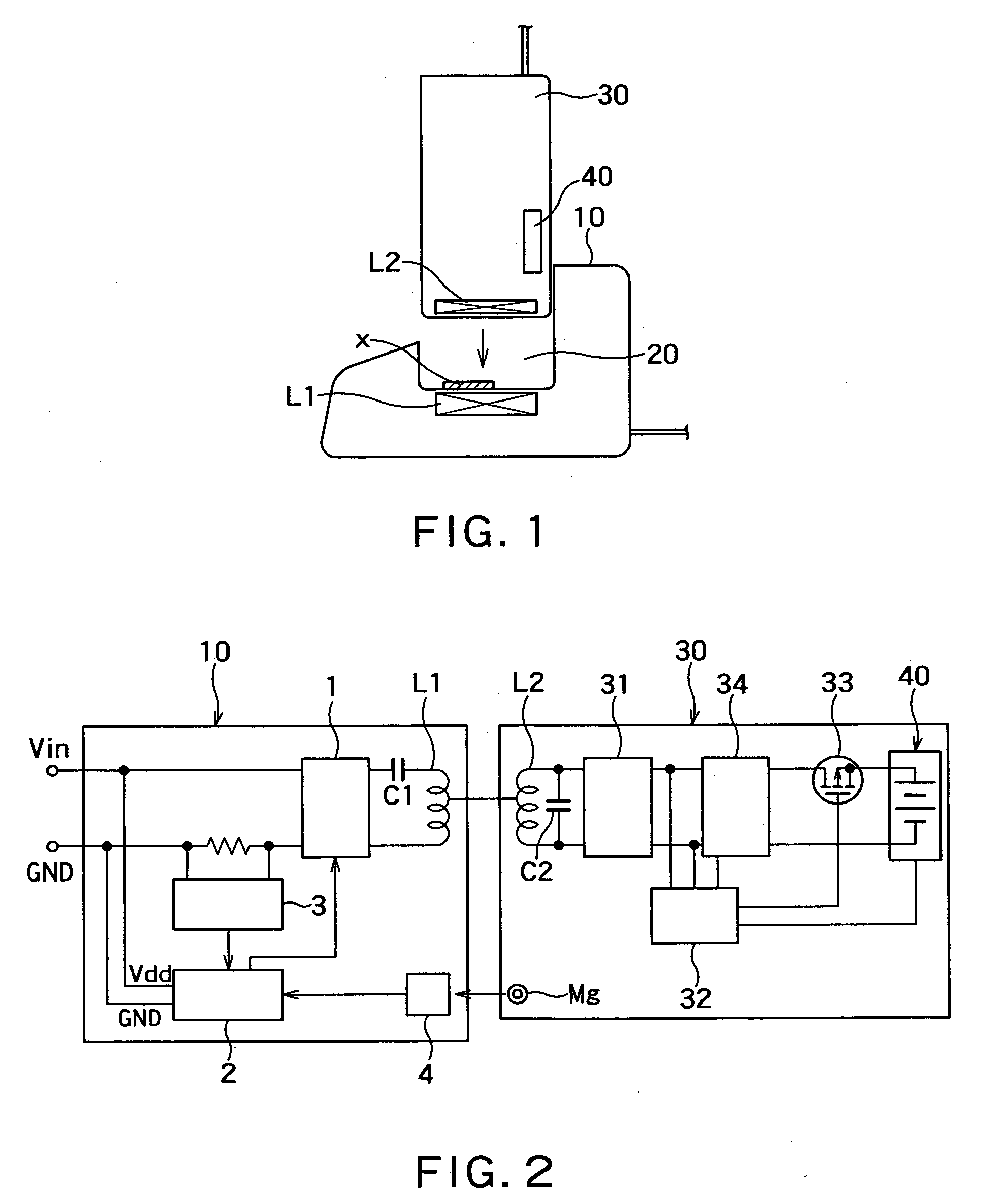
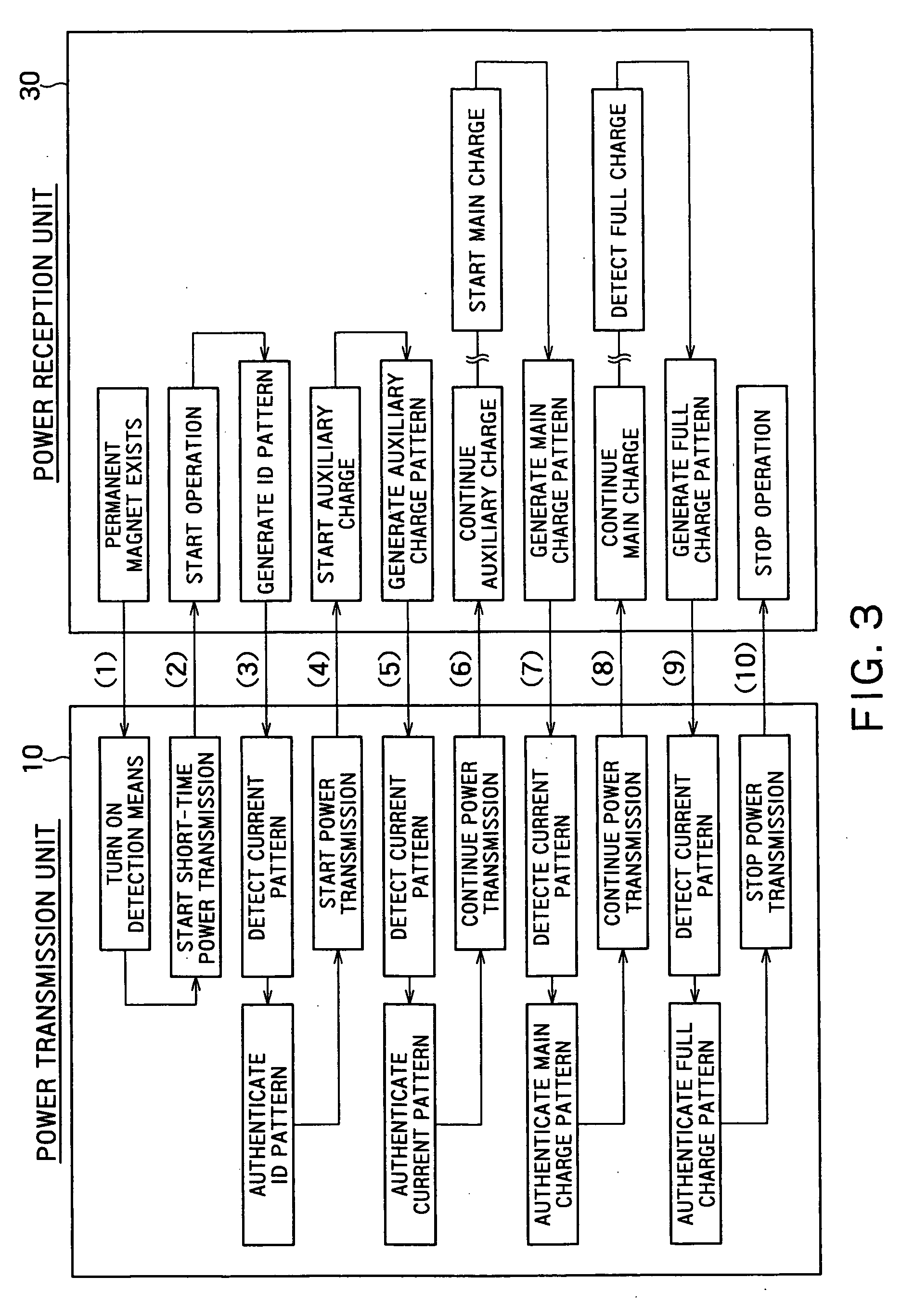
[0020]In addition, even when the unit detection means recognizes that the power reception unit is mounted on the support base properly, if the pulse pattern set by the second microcomputer in power transfer in the initial operation is not recognized by the current detection circuit of the power transmission unit, the power transfer is not performed. This can eliminate the risk of heat generation by the metal piece. Then, the apparatus can be restarted after correcting displacement or the like.

[0021]Further, even when the power reception unit is mounted properly,...


PUM


Abstract

There is provided a non-contact power transfer apparatus performing non-contact power transfer from a power transmission coil L1 to a power reception coil L2 using electromagnetic induction. The non-contact power transfer apparatus has: a power transmission unit 10 including the power transmission coil L1, a power transmission circuit 1, a current detection circuit 3, unit detection means 4 and a first microcomputer 2 with a control circuit for controlling each of the circuits; and a power reception unit 30 including the power reception coil L2, a rectification smoothing circuit 31, a series regulator 34, a charge battery unit 40 with a rechargeable battery, a switching element 33 for pulse-charging and a second microcomputer 32 with a control circuit for controlling the series regulator and the switching element.
With this structure, the non-contact power transmission apparatus can be safe, reduce unnecessary power loss and prevent heat generation even when a foreign matter like metal is placed close thereto.

Description

BACKGROUND OF THE INVENTION[0001]1. Field of the Invention[0002]The present invention relates to a non-contact power transfer apparatus for a power reception unit to non-contact charge a secondary battery built in an electronic device such as a portable device.[0003]2. Description of the Related Art[0004]As illustrated in FIG. 1, a typical non-contact power transfer apparatus includes a power transmission unit main body 10 having a power transmission coil L1 for power transmission built therein, and a support base 20 formed as a part of the main body for mounting a power reception unit 30 detachably thereon, the power reception unit 30 having a power reception coil L2 for power reception built therein. It is not preferable for safety reasons that the power transmission unit 10 starts power transfer before it recognizes that the power reception unit 30 is mounted at a predetermined position on the support base 20. For example, as illustrated in FIG. 1, assume that a metal piece x suc...

Claims


Application Information

Patent Timeline
IPC IPC(8): H01F38/14H02J7/00
CPCH01F27/365H02J7/025H01F38/14H02J50/10H02J7/00045H02J50/70H01F27/36H02J50/12H02J50/80H02J50/90
Inventor KOJIMA, HIDEKIFURUYA, HIROSHI
Owner MURATA MFG CO LTD
Why Eureka
Try Eureka