Thermal Management of LED Lighting Systems

a technology of led lighting and thermal management, which is applied in the direction of fixed installation, lighting and heating equipment, lighting support devices, etc., can solve the problems of basic function, led lighting system performance degradation, and lighting system less than 7,000 hours of li

Active Publication Date: 2010-05-20
ABL IP HLDG
View PDF91 Cites 130 Cited by
  • Summary
  • Abstract
  • Description
  • Claims
  • Application Information

AI Technical Summary

Problems solved by technology

In an LED light source, the heat generated by the lamp may cause problems related to the basic function of the lamp and light fixture.
Specifically, high operating temperatures degrade the performance of the LED lighting systems.
Typical LED lighting systems have lifetimes approaching 50,000 hours at room temperature; however, the same LED lighting system has a lifetime of less than 7,000 hours when operated at close to 90° C.
Traditional means of providing electrical and mechanical contact between LEDs and the light fixture provide poor means of conduction between the LEDs and external light fixture surfaces (such as die cast housing).
One disadvantage of using a thermally conductive structure within the light fixture envelope is that it allows dissipation of heat

Method used


Image

  • Thermal Management of LED Lighting Systems
  • Thermal Management of LED Lighting Systems
  • Thermal Management of LED Lighting Systems

Examples


Embodiment Construction

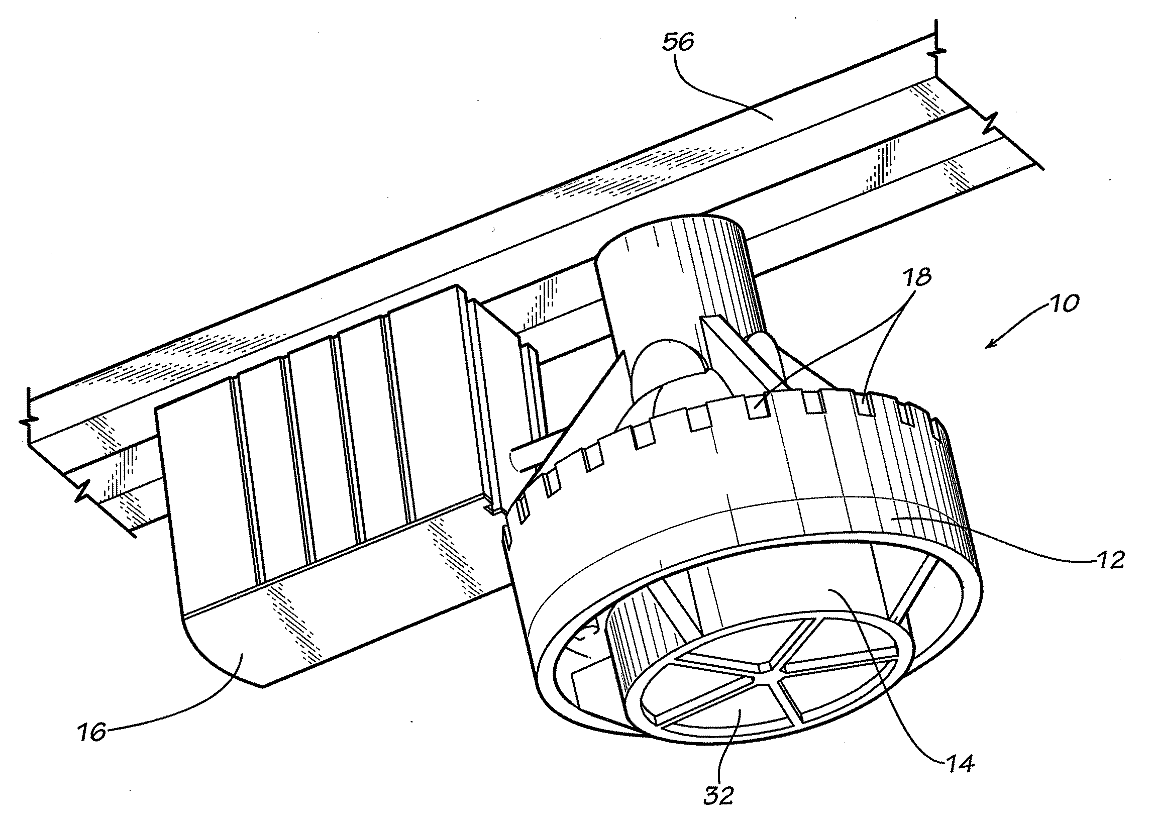
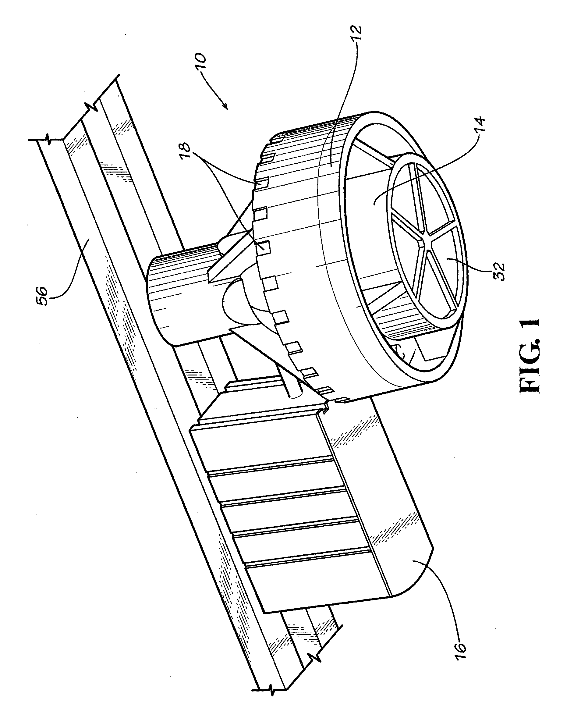
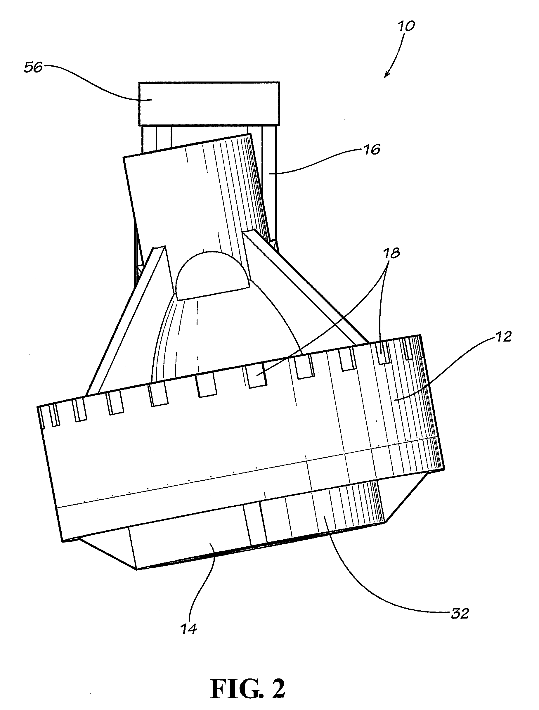
[0010]Embodiments of the invention provide thermal management systems for LED light fixtures. In one embodiment, an LED track light fixture includes a lighting assembly, a fixture housing mounted to the lighting assembly and having a plurality of apertures, and a mounting structure that affixes the fixture housing to a track. In this embodiment, the lighting assembly includes a heat sink with a plurality of fins, a reflector mounted on the heat sink, at least one light emitting diode supported on the heat sink, wherein the at least one light emitting diode is supported to emit light towards the reflector, and a synthetic jet actuator positioned adjacent the heat sink. In some embodiments, the at least one light emitting diode is positioned on a first side of a printed circuit board and a second side of the printed circuit board is mounted to a mounting surface on the heat sink. In some embodiments, a thermal interface material may be positioned between the printed circuit board and ...


PUM


Abstract

Embodiments of the invention provide thermal management systems for LED light fixtures. In one embodiment, an LED track light fixture includes a lighting assembly, a fixture housing mounted to the lighting assembly and having a plurality of apertures, and a mounting structure that affixes the fixture housing to a track. In this embodiment, the lighting assembly includes a heat sink, a reflector, at least one light emitting diode, and a synthetic jet actuator. In a second exemplary embodiment, a sealed, enclosed LED light fixture includes a lighting assembly, along with an enclosure and a fixture housing surrounding the lighting assembly. In this embodiment, the lighting assembly includes at least one light emitting diode, a thermoelectric cooler, and at least one heat sink. In some embodiments, a forced air cooling device may be located between the printed circuit board and the thermoelectric cooler.

Description

[0001]This application claims the benefit of U.S. Provisional Application No. 61 / 199,543, entitled “LED Track Light with Fanless Cooling,” filed Nov. 18, 2008, and U.S. Provisional Application No. 61 / 156,555, filed Mar. 2, 2009, entitled “Forced Air / Thermoelectric Cooling of Enclosed LEDs,” the entire contents of both of which are hereby incorporated by reference.FIELD OF THE INVENTION[0002]This invention relates to thermal management of light emitting diode-based lighting systems.BACKGROUND OF THE INVENTION[0003]A light emitting diode (“LED”) typically includes a diode mounted onto a die or chip, where the diode is surrounded by an encapsulant. The die is connected to a power source, which, in turn, transmits power to the diode. An LED used for lighting or illumination converts electrical energy to light in a manner that results in very little radiant energy outside the visible spectrum. In a typical LED, a significant portion of the current that is applied to the LEDs is subsequen...

Claims


Application Information

Patent Timeline
IPC IPC(8): F21S4/00
CPCF21S8/038F21S8/088F21V21/30F21V29/83F21Y2101/02F21V29/63F21V29/773F21V29/02F21Y2115/10F21V29/67
Inventor MILLER, MICHAEL R.
Owner ABL IP HLDG
Why Eureka
Try Eureka