Steam generator flow by-pass system

a technology of bypass system and steam generator, which is applied in the direction of nuclear reactors, nuclear elements, greenhouse gas reduction, etc., can solve the problems of nuclear reactor b>5/b> being shut down and being unable to generate electricity for an extended period of tim

Active Publication Date: 2010-05-20
NUSCALE
View PDF15 Cites 27 Cited by
  • Summary
  • Abstract
  • Description
  • Claims
  • Application Information

AI Technical Summary

Problems solved by technology

The latter two of these responses result in the nuclear reactor 5 being shut down and unable to generate electricity for an extended period of time.

Method used


Image

  • Steam generator flow by-pass system
  • Steam generator flow by-pass system
  • Steam generator flow by-pass system

Examples


Embodiment Construction

[0026]Various embodiments disclosed or referred to herein may be operated consistent, or in conjunction, with features found in co-pending U.S. application Ser. No. 11 / 941,024 which is herein incorporated by reference in its entirety.

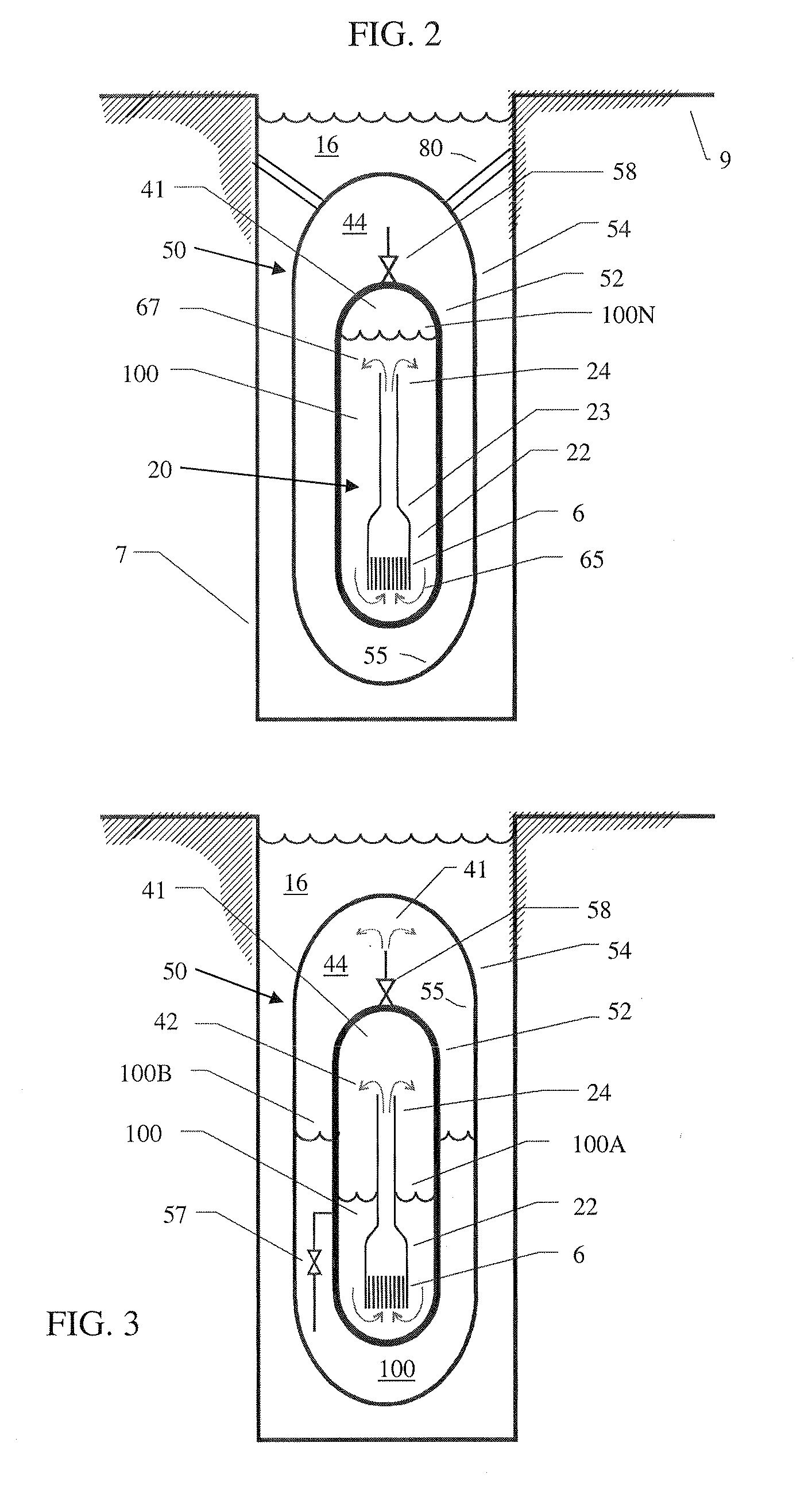
[0027]FIG. 2 illustrates a power module assembly 50 comprising an internally dry containment vessel 54. The containment vessel 54 is cylindrical in shape, and has spherical, domed, or ellipsoidal upper and lower ends. The entire power module assembly 50 may be submerged in a pool of water 16 which serves as an effective heat sink. The pool of water 16 and the containment vessel 54 may further be located below ground 9 in a reactor bay 7. The containment vessel 54 may be welded or otherwise sealed to the environment, such that liquids and gas do not escape from, or enter, the power module assembly 50. The containment vessel 54 may be supported at any external surface.

[0028]In one embodiment, the containment vessel 54 is suspended in the pool of water 16 ...


PUM


Abstract

A nuclear reactor module includes a reactor vessel and a reactor housing mounted inside the reactor vessel, wherein the reactor housing comprises a shroud and a riser located above the shroud. The nuclear reactor module further includes a heat exchanger proximately located about the riser, and a reactor core located in the shroud. A steam generator by-pass system is configured to provide an auxiliary flow path of primary coolant to the reactor core to augment a primary flow path of the primary coolant out of the riser and into the shroud, wherein the auxiliary flow path of primary coolant exits the reactor housing without passing by the heat exchanger.

Description

TECHNICAL FIELD[0001]The invention relates to a system for removing decay heat from a nuclear reactor.BACKGROUND[0002]In nuclear reactors designed with passive operating systems, the laws of physics are employed to ensure that safe operation of the nuclear reactor is maintained during normal operation or even in an emergency condition without operator intervention or supervision, at least for some predefined period of time. A nuclear reactor 5 includes a reactor core 6 surrounded by a reactor vessel 2. Water 10 in the reactor vessel 2 surrounds the reactor core 6. The reactor core 6 is further located in a shroud 122 which surround the reactor core 6 about its sides. When the water 10 is heated by the reactor core 6 as a result of fission events, the water 10 is directed from the shroud 122 and out of a riser 124. This results in further water 10 being drawn into and heated by the reactor core 6 which draws yet more water 10 into the shroud 122. The water 10 that emerges from the ri...

Claims


Application Information

Patent Timeline
Patent Type & Authority Applications(United States)
IPC IPC(8): G21C9/00
CPCG21C1/322Y02E30/40G21C15/26G21C15/18Y02E30/30G21C1/32
Inventor YOUNG, ERIC PAULGROOME, JOHN T.REYES, JR., JOSE N.
Owner NUSCALE
Why Eureka
Try Eureka