Bi-Directional Annulus Seal

a sealing and annulus technology, applied in the direction of sealing/packing, drilling pipes, borehole/well accessories, etc., can solve the problems of sealing to leak and sealing to leak, and achieve the effect of preventing galling of the seal

Active Publication Date: 2010-05-27
VETCO GRAY
View PDF25 Cites 46 Cited by
  • Summary
  • Abstract
  • Description
  • Claims
  • Application Information

AI Technical Summary

Benefits of technology

[0006]The seal ring of this technique forms a metal-to-metal seal and has features that lock the seal to the high pressure housing and the hanger. The seal ring also has features that enable retrieval without risk of seal disassembly. The seal ring has inner and outer walls separated by a slot. A metal energizing ring is pushed into the slot during installation to deform the inner and outer walls into sealing engagement with inner and outer wellhead members.
[0009]In the embodiment shown, a radial gap exists between the outer wall of the seal and the inner wall of the mating housing. Such gap is required for installation in the field and is sufficiently large to require plastic deformation of the seal body, but not the energizer rings. The soft metallic inserts may also prevent galling of the seal ring inner and outer members to their respective well pipe hanger and wellhead bore members. In order to accommodate sealing over scratches and surface trauma of the wellhead members, soft metallic inserts may be provided for on the seal. The size and thickness of the metallic inserts is sufficient to provide for scratch filling and therefore sealing between the mating members. The soft metallic inserts may also prevent galling of the seal ring inner and outer members to their respective casing / tubing hanger and wellhead bore members.

Problems solved by technology

A reduction in axial force on the energizing ring results in a reduction in the radial inward and outward forces on the inner and outer walls of the seal ring, which may cause the seal to leak.
A loss of radial loading between the seal and its mating surfaces due to thermal transients may also cause the seal to leak.

Method used


Image

  • Bi-Directional Annulus Seal
  • Bi-Directional Annulus Seal
  • Bi-Directional Annulus Seal

Examples


Embodiment Construction

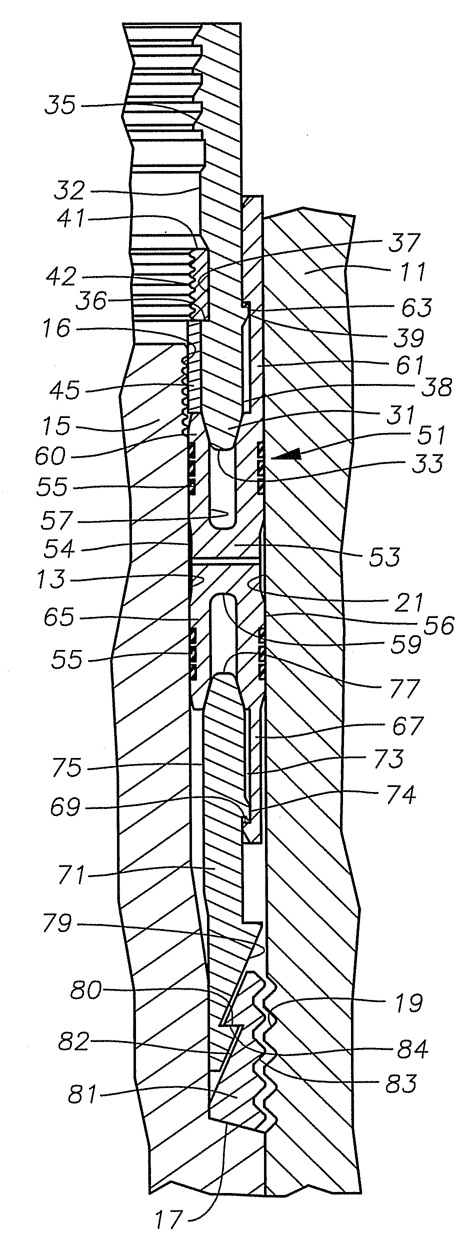
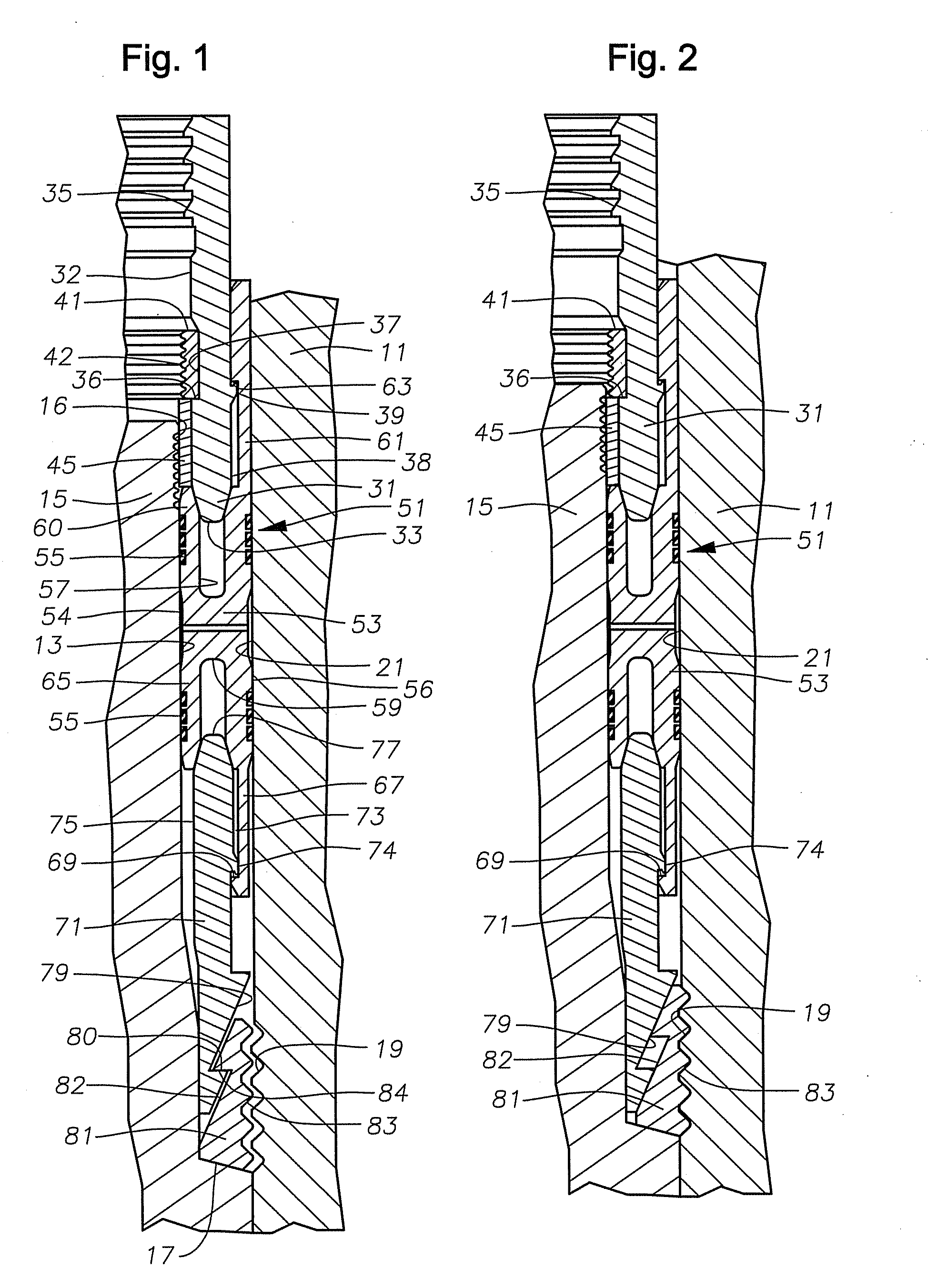
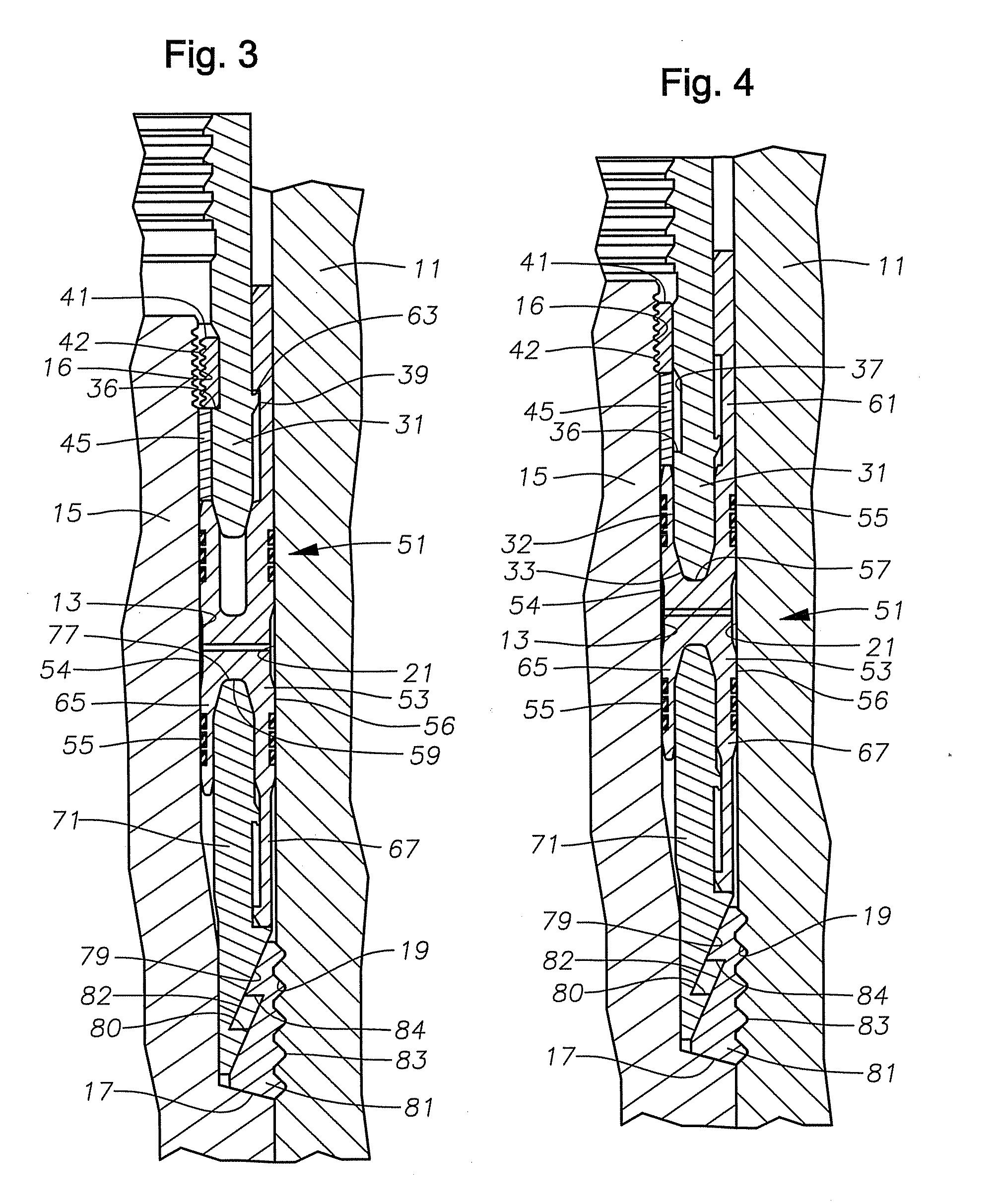
[0016]Referring to FIG. 1, a portion of a high pressure wellhead housing 11 is shown. Housing 11 is located at an upper end of a well and serves as an outer wellhead member in this example. Housing 11 has a bore 21 located therein. In this embodiment, grooves 19 are positioned along a length of the inner surface of housing 11 in bore 21. Grooves 19 comprise parallel load flanks extending around the inner diameter of bore 21.

[0017]In this example, the inner wellhead member comprises a casing hanger 15, which is shown partially in FIG. 1 within bore 21. Alternately, wellhead housing 11 could be a tubing spool or a Christmas tree. Alternately, casing hanger 15 could be a tubing hanger, plug, safety valve or other device. Casing hanger 15 has an exterior annular recess radially spaced inward from bore 21 to define a seal pocket 13. In this embodiment, teeth 16 are positioned along a length of the outer surface of casing hanger 15, in seal pocket 13. Teeth 16 comprise parallel annular gr...


PUM


Abstract

A wellhead seal assembly forms a metal-to-metal seal between inner and outer wellhead members. A metal seal ring has inner and outer walls separated by a slot. A lock ring has grooves for locking the inner wellhead member to the outer wellhead member during installation. An energizing ring has a C-ring captured on its inner surface. When the energizing ring is moved further into the slot, the C-ring is forced from its pocket and engages the surface of the inner wellhead member, locking the seal assembly to the inner wellhead member.

Description

CROSS-REFERENCE TO RELATED APPLICATION [0001]This application claims priority to provisional application 61 / 117,879, filed Nov. 25, 2008.FIELD OF THE INVENTION [0002]This technique relates in general to wellhead assemblies and in particular to a seal for sealing between inner and outer wellhead members.BACKGROUND OF THE INVENTION [0003]Seals are used between inner and outer wellhead tubular members to contain internal well pressure. The inner wellhead member may be a tubing hanger that supports a string of tubing extending into the well for the flow of production fluid. The tubing hanger lands in an outer wellhead member, which may be wellhead housing, a Christmas tree, or tubing head. A packoff or seal seals between the tubing hanger and the outer wellhead member. Alternately, the inner wellhead member might be a casing hanger located in a wellhead housing and secured to a string of casing extending into the well. A seal or packoff seals between the casing hanger and the wellhead h...

Claims


Application Information

Patent Timeline
Patent Type & Authority Applications(United States)
IPC IPC(8): E21B33/03E21B33/04
CPCE21B2033/005E21B33/04E21B2200/01
Inventor ELLIS, STEVEN C.GARCIA, JR., JAVIERHUNTER, RICK C.NELSON, JOHN E.
Owner VETCO GRAY
Why Eureka
Try Eureka