Plunger piston

a technology of a piston and a piston body, which is applied in the direction of vibration dampers, mechanical devices, transportation and packaging, etc., can solve the problems of limiting the available air volume of the hollow body, unfavorable air oscillations in the region, etc., and achieves the effect of simple design and easy production

Inactive Publication Date: 2010-05-27
LKH KUNSTWERK
View PDF13 Cites 30 Cited by
  • Summary
  • Abstract
  • Description
  • Claims
  • Application Information

AI Technical Summary

Benefits of technology

[0005]One object of this invention is to provide a plunger piston of the type mentioned above but which has a simple design and is easy to produce.
[0007]The cup-shaped lower part can be easily produced and forms the lower airtight closure of the hollow body. The upper part can be placed like a cover onto the lower part, thus delimiting the cavity defined by the hollow body. The upper part with its connecting edge forms the coupling point for the bellows. It is thus possible to control the introduction of force from the upper part to the lower part by the embodiment of the upper part. In particular, a load transfer can be carried out, if so desired, from the upper part directly into the circumferential casing part of the lower part. This permits a simpler and more stable design of the plunger piston.
[0010]An airtight connection of the lower part to the upper part can be achieved in a simple fashion if the lower part and the upper part each has a circumferential edge and the upper part with the lower part are joined to each other at the edges by a sealed connection.
[0012]The design of the upper part achieves a more stable structure because the reinforcing elements of the upper part are formed integrally onto the connecting edge and protrude into the air passage region enclosed by the connecting edge and because at least part of the reinforcing elements, in their region remote from the connecting edge, are connected to a reinforcing part. This design makes it possible to reliably absorb and transfer radially acting clamping forces of the bellows.
[0018]According to one embodiment of this invention, the bottom of the lower part has a reinforcing element coupled to the bottom or embedded into the bottom, for example during the plastic injection-molding process. The reinforcing element stiffens the bottom at least partially. The transmission of force to a connected axle or body component is thus improved. This is accompanied by advantages with regard to the distribution of force if the bottom is not resting with its entire surface area against the axle / body component.

Problems solved by technology

When rapid load changes occur, undesirable air oscillations can occur in the region of these air passage openings.
In addition, the inner circumference wall takes up space and thus limits the available air volume of the hollow body.

Method used


Image

  • Plunger piston
  • Plunger piston
  • Plunger piston

Examples


Embodiment Construction

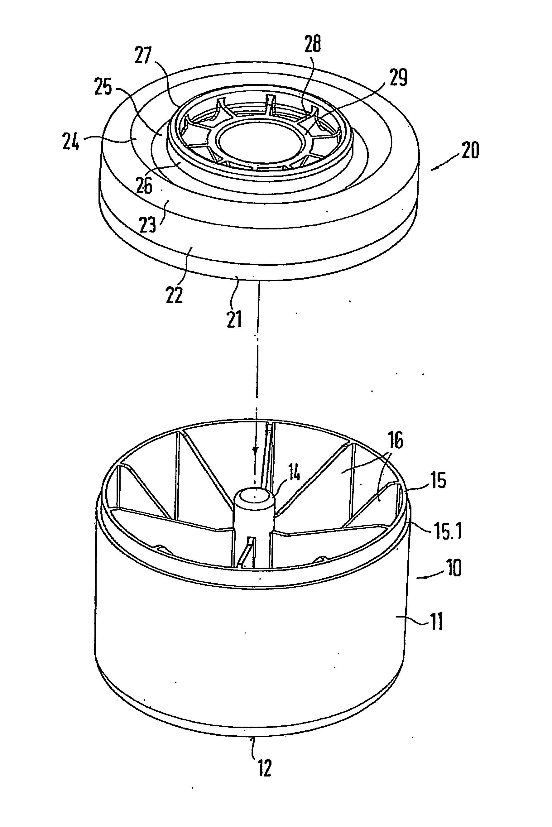
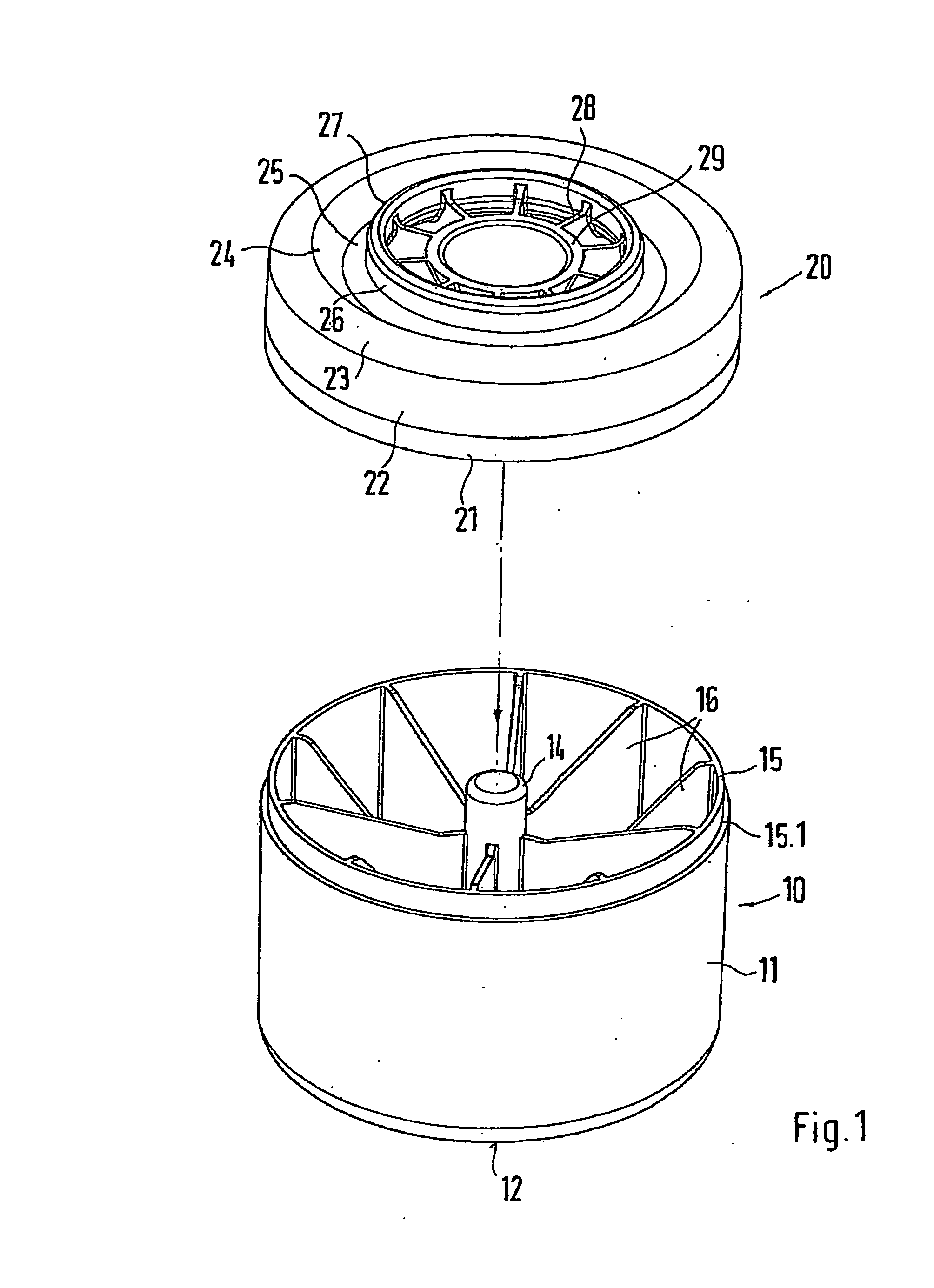
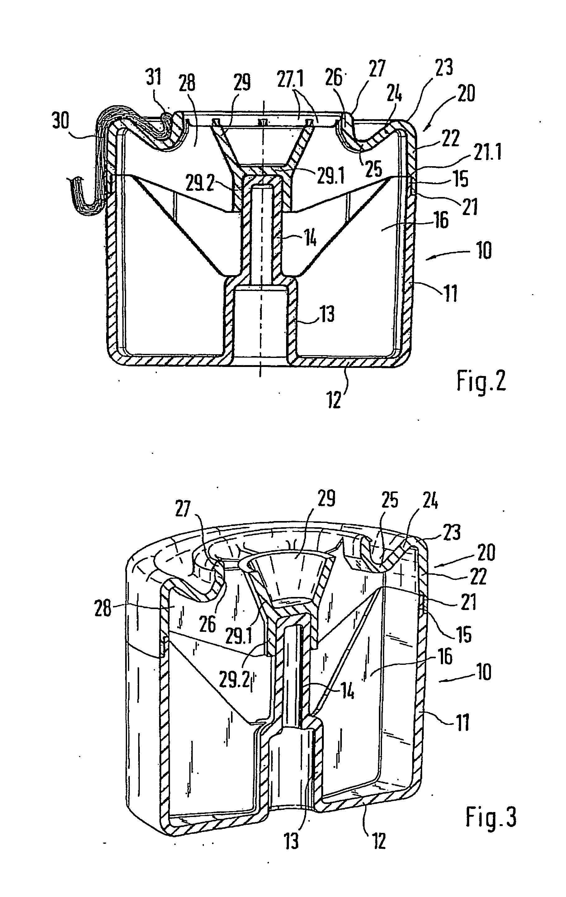
[0025]FIG. 1 shows a plunger piston comprised of a lower part 10 and an upper part 20. The structural embodiment of these two components is shown in greater detail in FIG. 2. Accordingly, the lower part 10 has a bottom 12 onto which a circumferential casing part 11 is integrally formed. A fastening receptacle 13 is also formed centrally onto the bottom 12. The fastening receptacle 13 encloses a receiving space into which a fastening element such as a nut can be inserted and the cylindrical fastening receptacle 13 transitions into a counterpart support part 14 that is centrally formed.

[0026]The counterpart support part 14 encloses a receiving region. A fastening screw that is screwed into the nut of the fastening receptacle 13 is accommodated with its thread in the counterpart support part 14.

[0027]The circumferential, cylindrical casing part 11 has a circumferential edge 15. The edge 15 is formed by a step-like cross-sectional reduction of the casing part 11.

[0028]Reinforcing elemen...


PUM


Abstract

A plunger piston for an air spring. The plunger piston is designed as a hollow body and has a base to which an encircling casing part is indirectly or directly coupled. The plunger piston has, at its cover region which faces away from the base, a connecting edge for a bellows and at least one air passage opening. In order to produce this type of a plunger piston in a simple manner with little structural expenditure, the hollow body of this invention has a pot-shaped lower part which forms the base and the casing part. An upper part is placed onto the lower part and is connected to the lower part in an air-tight fashion, and the upper part has the connecting edge.

Description

BACKGROUND OF THE INVENTION[0001]1. Field of the Invention[0002]This invention relates to a plunger piston for an air spring, which plunger piston is formed as a hollow body and has a bottom to which a circumferential casing part is indirectly or directly coupled, and a plunger piston, in its cover region remote from a bottom, has a connecting edge for a bellows and at least one air passage opening.[0003]2. Discussion of Related Art[0004]A plunger piston of this kind is known from U.S. Pat. No. 6,386,524 B1, wherein a hollow body is formed by two circumferential walls. An inner circumferential wall is situated concentric to an outer circumferential wall. The two circumferential walls are supported in relation to each other by reinforcing ribs. The inner circumferential wall encompasses an air passage opening in the cover region of the plunger piston. The air passage opening is delimited by an edge to which a bellows can be fastened. The bottom region of the plunger piston can be sea...

Claims


Application Information

Patent Timeline
Patent Type & Authority Applications(United States)
IPC IPC(8): F16F9/05
CPCF16F9/057B60G2206/424B60G2206/014
Inventor EISE, MARTINSTEDRON, HORST
Owner LKH KUNSTWERK
Why Eureka
Try Eureka