
Digitally Controlled CML Buffer

a buffer and digital control technology, applied in the field of digital control of cml buffers, can solve the problems of limiting the amount of bias voltage driven, time is often too long to meet the speed requirements of current high speed systems, and the drawback of not being able to be switched quickly

Inactive Publication Date: 2010-05-27
POLARIS INNOVATIONS
View PDF6 Cites 7 Cited by
  • Summary
  • Abstract
  • Description
  • Claims
  • Application Information

AI Technical Summary

Benefits of technology

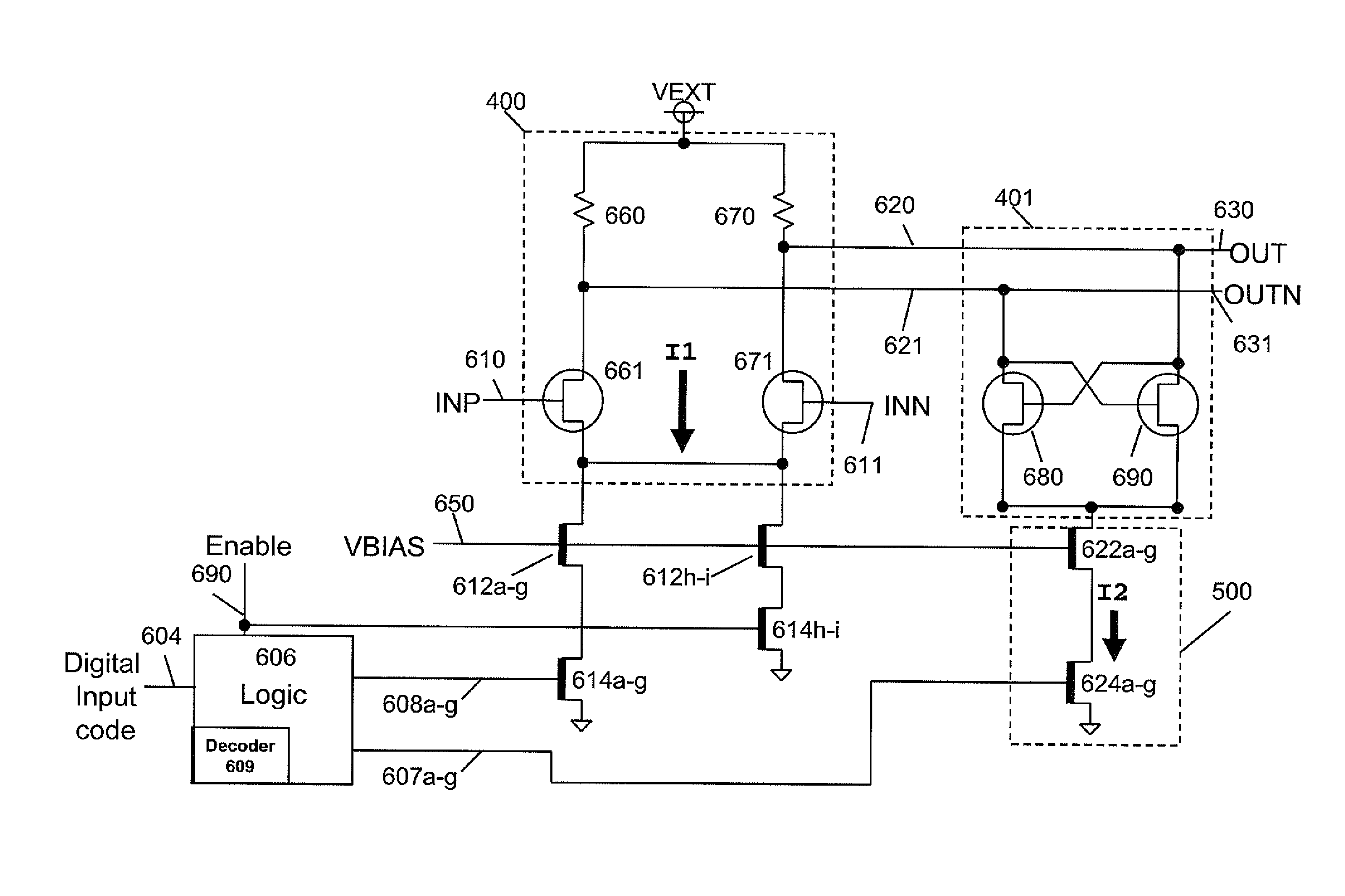
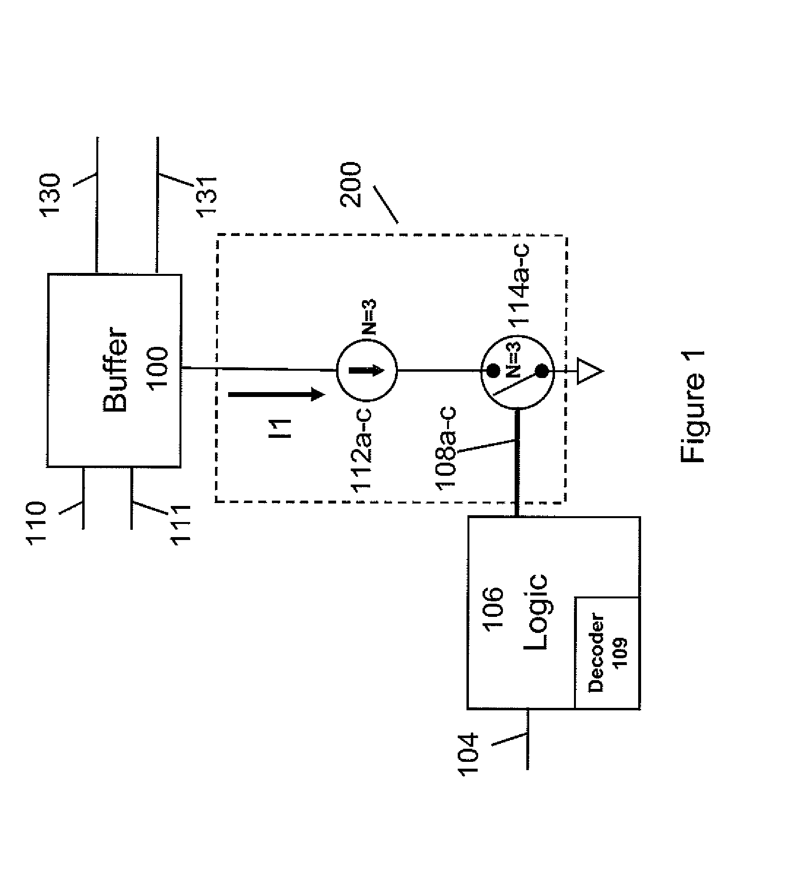
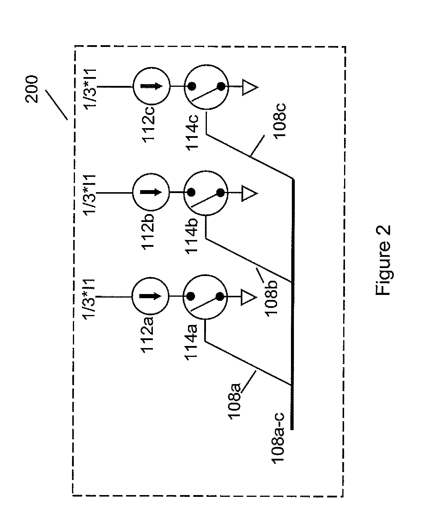
[0003]Embodiments of the invention generally provide circuits and methods of creating a delay of a current mode logic delay buffer including a differential stage, a biasing circuit arranged to provide a tail current for the differential stage, a switching arrangement connected in series with the biasing circuit and a logic device configured to selectively control the switching arrangement to vary the tail current to control the response time of the current mode logic delay buffer.

Problems solved by technology

This time is often too long to fulfill the speed requirements of current high speed systems.
In addition, there is a limit to how low or high the bias voltage can be driven and still have the buffer switch properly and the delay not suffer from non-monotonic behavior.
The addition of this analog tuning voltage has the drawback of not being able to be switched quickly.
As a result of introducing another analog tuning voltage, achieving a desired performance is difficult.

Method used


Image

  • Digitally Controlled CML Buffer
  • Digitally Controlled CML Buffer
  • Digitally Controlled CML Buffer

Examples


Embodiment Construction

[0011]Embodiments of the invention generally provide techniques for achieving accurate digital control of programmable CML delays. The programmable delay may be controlled to provide uniform or non-uniform resolution. For example, the techniques may provide for incremental delay with substantially equal increments. For some embodiments, linear resolution may be achieved by controlling the biasing current ratio between two stages. The techniques described herein may be utilized in a wide variety of applications that benefit from programmable delay. As an example, memory devices, such as dynamic random access memory (DRAM) devices, often utilize programmable delay elements in delay locked loops (DLLs) and / or phase locked loops (PLLs) used to achieve a desired relationship between externally supplied control signals (e.g., clock or data strobe signals) and corresponding internally generated control signals used to access (read / write) storage elements of the memory device. However, thos...


PUM


Abstract

Techniques and corresponding circuits for achieving programmable delay of a current mode logic delay buffer are provided. The techniques provide for incremental delay with substantially equal increments Delay may be achieved through the use of a circuit arrangement that allows biasing current to be controlled effect the response time of the circuit by digital control.

Description

BACKGROUND OF THE INVENTION[0001]1. Description of the Related Art[0002]Current mode logic (CML) delay elements are often utilized in high speed computing systems, phase locked loops (PLLs) and delay locked loops (DLLs) to achieve a desired relationship between speed and high resolution. In order to obtain high speed, low swing performance conventional CML buffers consist of a single stage differential amplifier with a resistive load. The propagation delay through a conventional CML delay element is based solely on the amount of bias voltage supplied to the current source. The biasing voltage used to create the tail current by analog adjustment cannot be changed quickly since the voltage is usually generated by an on-chip analog reference which could have a large capacitive load which must be charged and discharged in order to change the level. This time is often too long to fulfill the speed requirements of current high speed systems. In addition, there is a limit to how low or hig...

Claims


Application Information

Patent Timeline
Patent Type & Authority Applications(United States)
IPC IPC(8): H03H11/26
CPCH03K5/133
Inventor LEWISON, RICHARD
Owner POLARIS INNOVATIONS
Learn More