Eureka AIR delivers breakthrough ideas for toughest innovation challenges, trusted by R&D personnel around the world.

Touch-sensitive pointing device with guiding lines

a pointing device and touch-sensitive technology, applied in the direction of instruments, electric digital data processing, cathode-ray tube indicators, etc., can solve the problems of increasing the difficulty of controlling the cursor during horizontal movements, affecting the accuracy of the pointing device, so as to reduce the need for fine motor skills, simplify the fine adjustment task, and reduce the strain on the user's fingers, hand and/or arm

Active Publication Date: 2010-05-27
JENSEN JENS MARTIN
View PDF12 Cites 63 Cited by
  • Summary
  • Abstract
  • Description
  • Claims
  • Application Information

AI Technical Summary

Benefits of technology

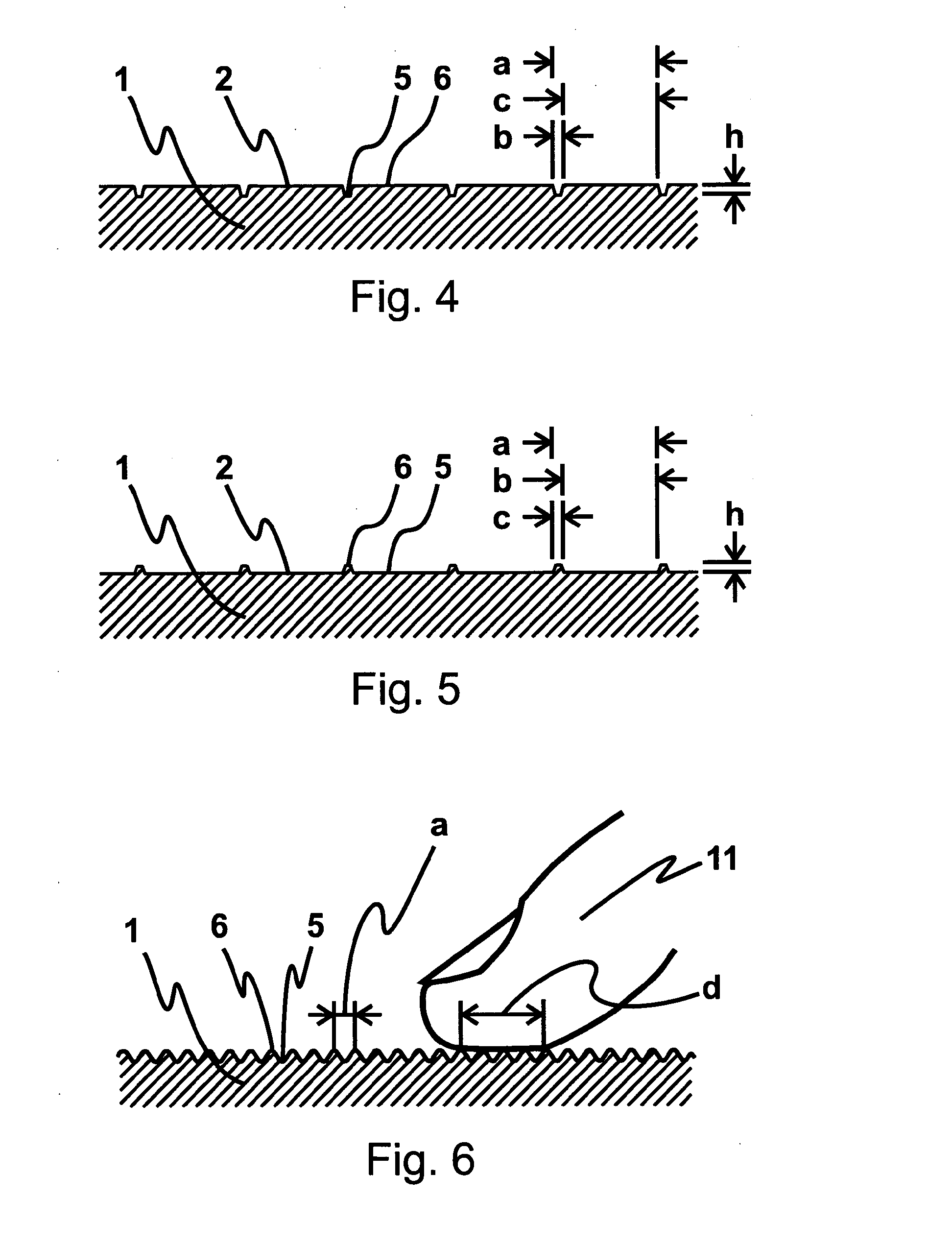
[0018]When a number of parallel guiding lines in the form of alternating ridges and grooves are provided with a distance between them that is narrower than the area of contact of a finger contacting the sensor surface, the finger tip is supported by a plurality of ridge tops at a time. The finger can easily glide freely, i.e. in any direction, on the sensor surface and thus e.g. control the movement of a cursor freely, i.e. in any direction, while, at the same time, it is possible at any time to lock the movement in a direction parallel to the guiding lines by increasing the pressure of the finger slightly.
[0033]Breaking the movement up in two independent steps simplifies the fine adjustment task, thereby substantially reducing need for fine motor skills, and as a consequence reducing the strain on the user's fingers, hand and / or arm.

Problems solved by technology

Many computer programs have a broad margin for correctly controlling the cursor during vertical movements, whereas controlling the cursor during horizontal movements is more problematic.
Recent studies have shown that the use of touchpads may lead to injuries substantially corresponding to so-called mouse injuries, the injury merely being to other muscles and tendons.
Being forced to use a touchpad when working on a laptop is thus usually a source of irritation.
In addition, the use of common touchpads poses problems for people with disabilities.

Method used


Image

  • Touch-sensitive pointing device with guiding lines
  • Touch-sensitive pointing device with guiding lines
  • Touch-sensitive pointing device with guiding lines

Examples


Embodiment Construction

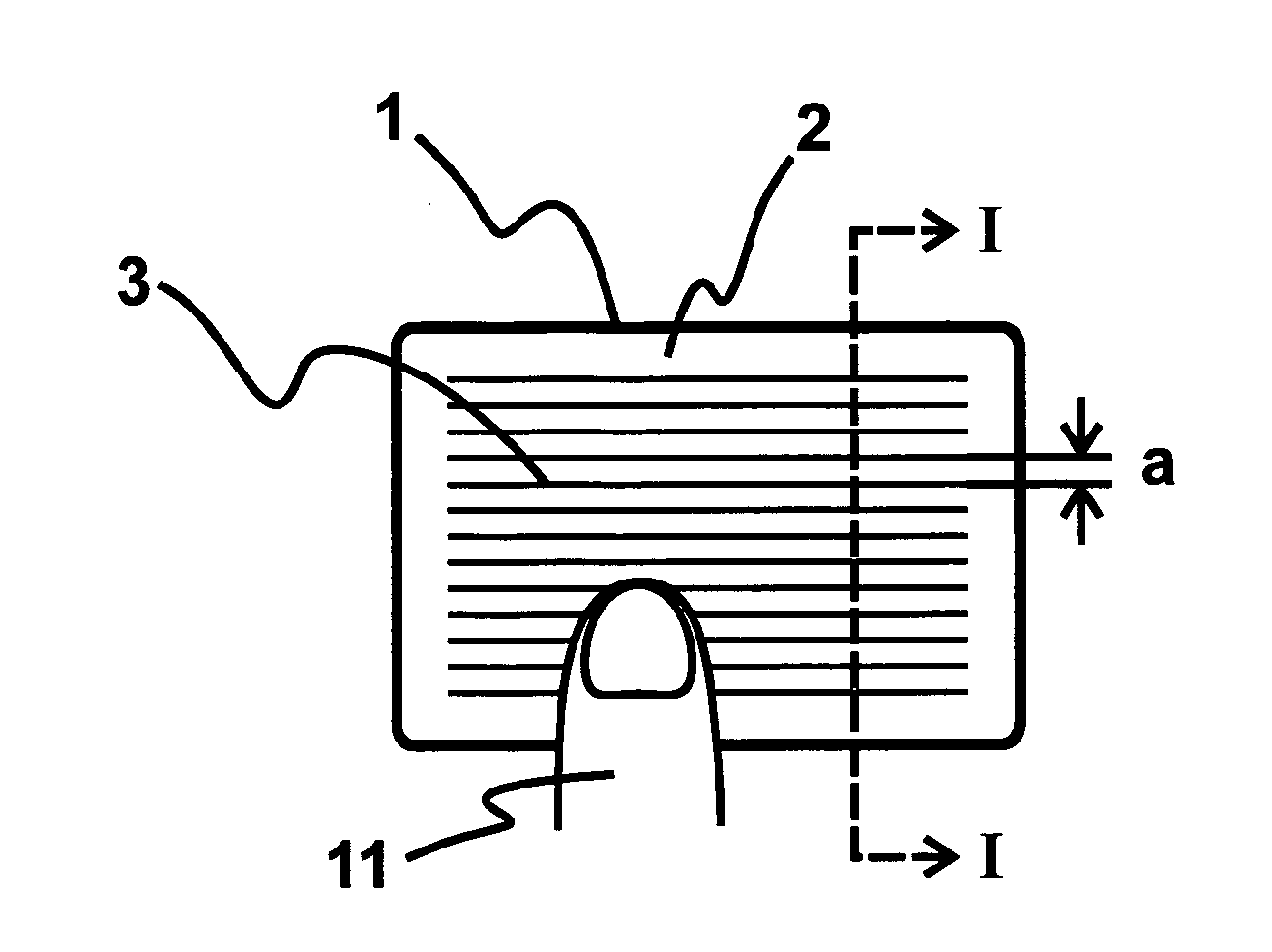
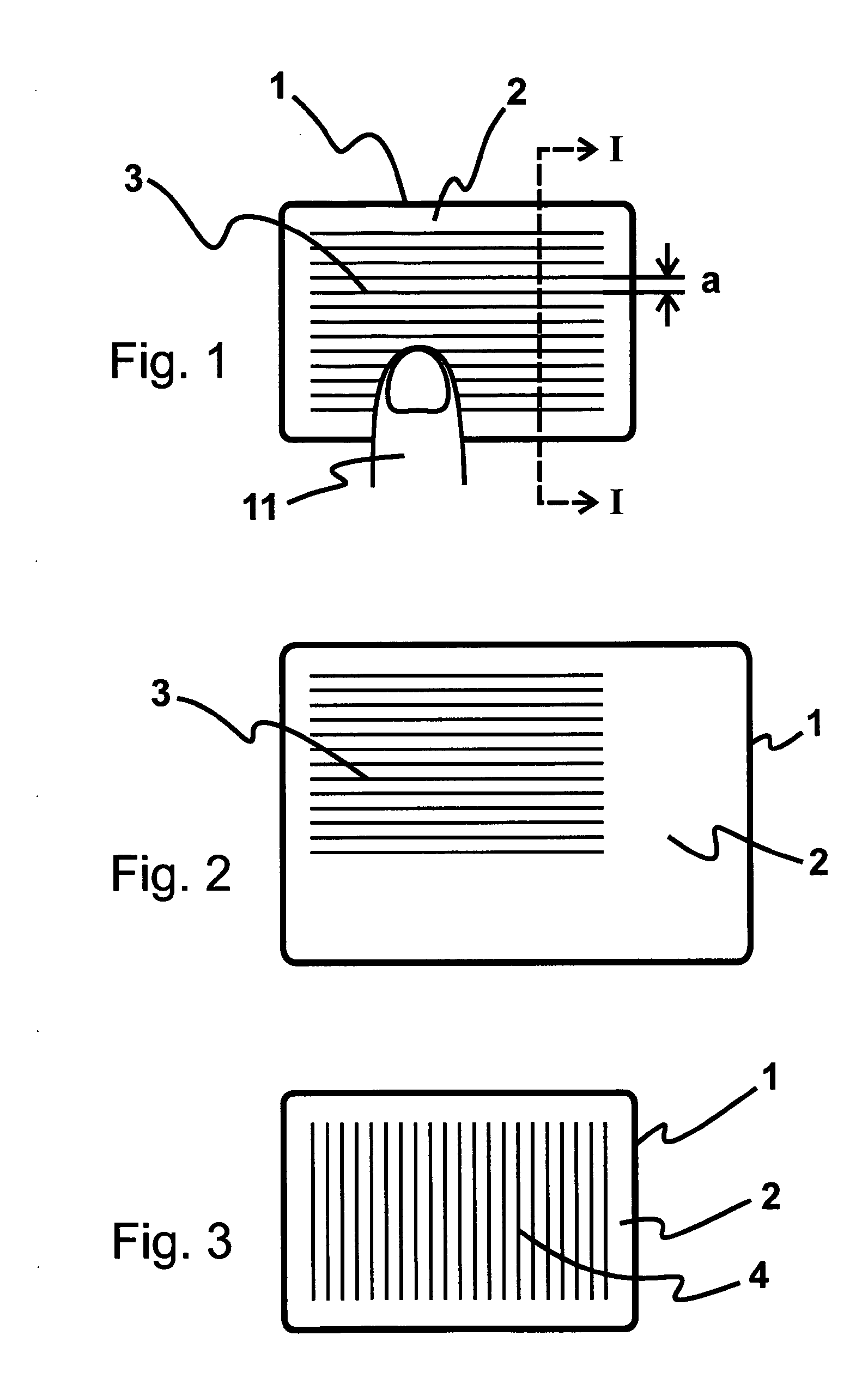
[0054]Schematically and seen from above, FIG. 1 shows a touchpad1 according to the invention with a sensor surface 2 an area of which is provided with a number of straight guiding lines 3 extending mutually parallel in a first direction. The guiding lines 3 are distributed over the entire area and the number of guiding lines may for example be determined by the distance a between them in relation to the size of the area.

[0055]The first direction may be defined as corresponding to a first preferred direction of the movement controlled by means of the touchpad 1, e.g. the movement of a cursor on a computer screen in a horizontal direction.

[0056]In the embodiment shown in FIG. 1, the area with the guiding lines 3 substantially covers the entire sensor surface 2.

[0057]Contrary to this, FIG. 2 shows an embodiment in which the area with the guiding lines 3 only partly covers the sensor surface, leaving smooth, uncorrugated areas. It is thus possible optionally to use the touchpad 1 in a t...


PUM


Abstract

A touchpad-or touch screen-based device has a touch-sensitive sensor surface and can generate electrical and / or optical signals dependent on the placement and / or movement of a finger physically contacting the sensor surface. The sensor surface comprises a corrugated surface in at least one sub-area, thereby providing a user with two modes for finger movement across the sensor surface, namely a first mode for sliding movement at a first finger pressure, and a second mode for guided movement at a second finger pressure higher than the first finger pressure.

Description

TECHNICAL FIELD[0001]The invention relates to a touch-sensitive pointing device for controlling at least two coordinates of a movement, said pointing device being provided with a touch-sensitive sensor surface generating electrical and / or optical signals dependent on the placement and / or movement of a finger in physical contact with the sensor surface.[0002]The invention further relates to a method for moving a cursor on a computer display from a first cursor position to a second cursor position in response to a finger's movement on a touch-sensitive sensor surface of a touch-sensitive pointing device.BACKGROUND[0003]Touch-sensitive sensor surfaces, such as a touchpad on a laptop or a touch screen, that generate signals dependent on the placement and / or movement of a finger physically contacting the sensor surface, are known in the art. The movement of the finger may be defined in terms of direction, speed and / or acceleration. Known sensor surfaces that are adapted to record a finge...

Claims


Application Information

Patent Timeline
IPC IPC(8): G06F3/033G06F3/0354G06F3/048G06F3/0488
CPCG06F3/03547G06F2203/04809G06F3/04886G06F3/0488G06F3/038G06F3/0481
Inventor JENSEN, JENS MARTIN
Owner JENSEN JENS MARTIN
Why Eureka
Eureka Blog
Learn More