Imaging device and imaging method

a technology of imaging device and image, which is applied in the direction of instruments, television systems, and exposure control, etc., can solve the problems of subject movement, multi-focus imaging is difficult to perform instantaneously, and the image is difficult to obtain a reasonable imag

Inactive Publication Date: 2010-05-27
SONY CORP
View PDF2 Cites 69 Cited by
  • Summary
  • Abstract
  • Description
  • Claims
  • Application Information

AI Technical Summary

Benefits of technology

[0031]According to the embodiments of the present invention described above, the multifocus imaging can be performed without missing the photo opportunity.

Problems solved by technology

However, in the camera mounted with the auto focus mechanism of the related art, the multifocus image is not recorded in time of imaging even if the user desires an image re-focused on a different subject (focal position) after imaging, and thus the desired image is not provided.
A method of generating a re-focused image by synthesizing a plurality of images has been proposed, but a reasonable image is very difficult to obtain with the image generated through the synthesis process.
However, the multifocus imaging is realistically difficult to perform instantaneously since a plurality of images is imaged and recorded while changing the focal position.
Therefore, the image obtained in the last half of the multifocus imaging is imaged after a predetermined time has elapsed from the release operation, and thus the subject may move during the time and a photo opportunity may be missed.

Method used


Image

  • Imaging device and imaging method
  • Imaging device and imaging method
  • Imaging device and imaging method

Examples


first embodiment

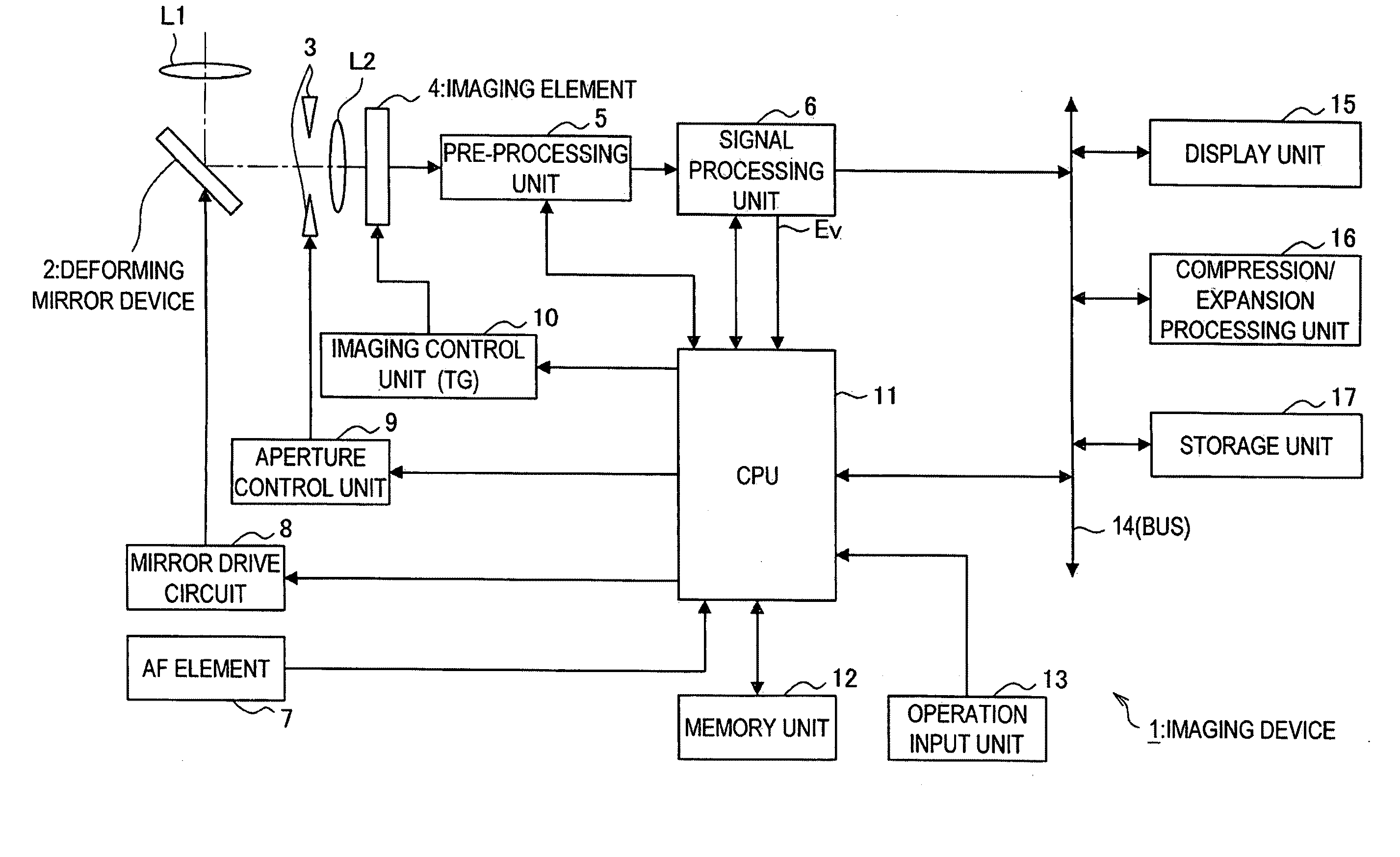
[0085]An imaging device and an imaging method according to a first embodiment of the present invention will be described below. The imaging device according to the first embodiment has a characteristic in performing the AF process to detect a focused position to a desired subject, and performing the entire area focus imaging while changing the focal position with the detected focused position as a reference in response to the subsequent release instruction.

[0086]In other words, the imaging device according to the present embodiment detects the focused position focused on a desired subject by performing the AF process for focusing on the desired subject in the imaging range in response to the detection instruction. Thereafter, the imaging device records the image data obtained by imaging the subject image at the detected focused position in the recording medium as the saving image data in response to the release instruction. The imaging device also performs the entire area focus imag...

second embodiment

[0223]A second embodiment of the present invention will be described below. The second embodiment differs from the first embodiment in that the bracket imaging is performed during the period from the detection instruction to the release instruction, but other functional configurations are substantially the same as the first embodiment, and thus the detailed description thereof will be omitted.

[0224]First, the focus control by the imaging device 1 according to the present embodiment will be described in detail with reference to FIG. 15.

[0225]The imaging device 1 according to the second embodiment detects the focused position by performing the AF process in response to the detection instruction, and performs the bracket imaging during the period from when the detection of the focused position is completed until the release instruction is made. In the bracket imaging, the imaging device 1 periodically changes the focal position within a predetermined range having the focused position d...

third embodiment

[0246]The third embodiment of the present invention will now be described. The third embodiment differs from the second embodiment in that the subject detection process is performed in response to the detection instruction and the bracket imaging is performed within the range of the focused position detected in the subject detection process, and other functional configurations are the same as the second embodiment and thus the detailed description will be omitted.

[0247]The imaging device 1 according to the third embodiment performs the subject detection process in response to the detection instruction (e.g., half-press operation of release button). In this detection process, the focal position is changed in the focusable range, and the image data obtained by imaging the subject image at a plurality of changed different focal positions while performing such change is analyzed to obtain the evaluation parameter for subject detection. The imaging device 1 thereby detects one or more su...


PUM


Abstract

There is provided an imaging device which detects a focused position focused on a desired subject in an imaging range in response to a detection instruction, acquires the image data obtained by imaging the subject image at the focused position as saving image data in response to a release instruction, and sequentially changing a focal position with the focused position as a reference and acquiring the image data obtained by imaging the subject image at a plurality of changed different focal positions as saving image data.

Description

BACKGROUND OF THE INVENTION[0001]1. Field of the Invention[0002]The present invention relates to an imaging device, and an imaging method.[0003]2. Description of the Related Art[0004]Digital still cameras generate digital image data by converting a subject image (optical image) entered to an image sensor to an electrical signal, and record the digital image data on a recording medium such as a memory card according to a release operation of the imager. The digital still camera is generally mounted with an auto focus (automatic focus) mechanism and adopts an optical system having a large F value and a deep depth of field to facilitate the focusing. The imager thus can image the subject image focused on a subject by the auto focus mechanism and record the digital image data of the subject image by simply operating the release button with the digital still camera directed towards the subject.[0005]Japanese Patent Application Laid-Open No. 2003-143461 discloses a digital still camera th...

Claims


Application Information

Patent Timeline
Patent Type & Authority Applications(United States)
IPC IPC(8): H04N5/232G02B7/28G02B7/36G03B7/00G03B13/36H04N101/00
CPCH04N23/672H04N23/673H04N23/676H04N23/743
Inventor NAGASAKA, HIDEOAOKI, SUNAOYAMADA, MASAHIRO
Owner SONY CORP
Why Eureka
Try Eureka