
Image forming apparatus and cooling method used therein

Active Publication Date: 2010-05-27
RICOH KK
View PDF7 Cites 37 Cited by
  • Summary
  • Abstract
  • Description
  • Claims
  • Application Information

AI Technical Summary

Problems solved by technology

When the temperature inside the image forming apparatus is increased beyond a certain point due to the heat generated by those heat generators, the toner used to develop images might coagulate, resulting in substandard images.
However, at present, the amount of space available between the various components inside the image forming apparatus continues to shrink due to increasing demand for more compact image forming apparatuses, and accordingly it is difficult to secure sufficient space for installing the air duct to cool the hot portions in the apparatus.
Because the cost of the liquid-cooing device is higher, usage of the liquid-cooling devices is limited to the above-described portions, and the air-cooling devices are used instead in such portions that can be cooled sufficiently by the air-cooling device and have sufficient space for installing the air duct.
However, the above-described known image forming apparatus including both the air-cooling device and the liquid-cooling device has a drawback in that, because separate air-suction ducts each provided with an air-suction port are necessary for the cooling fan of the air-cooling device and that of the liquid-cooling device, the number of components increases, resulting in an increases in the size as well as the cost of the apparatus.

Method used


Image

  • Image forming apparatus and cooling method used therein
  • Image forming apparatus and cooling method used therein
  • Image forming apparatus and cooling method used therein

Examples


Embodiment Construction

[0033]In describing preferred embodiments illustrated in the drawings, specific terminology is employed for the sake of clarity. However, the disclosure of this patent specification is not intended to be limited to the specific terminology so selected, and it is to be understood that each specific element includes all technical equivalents that operate in a similar manner and achieve a similar result.

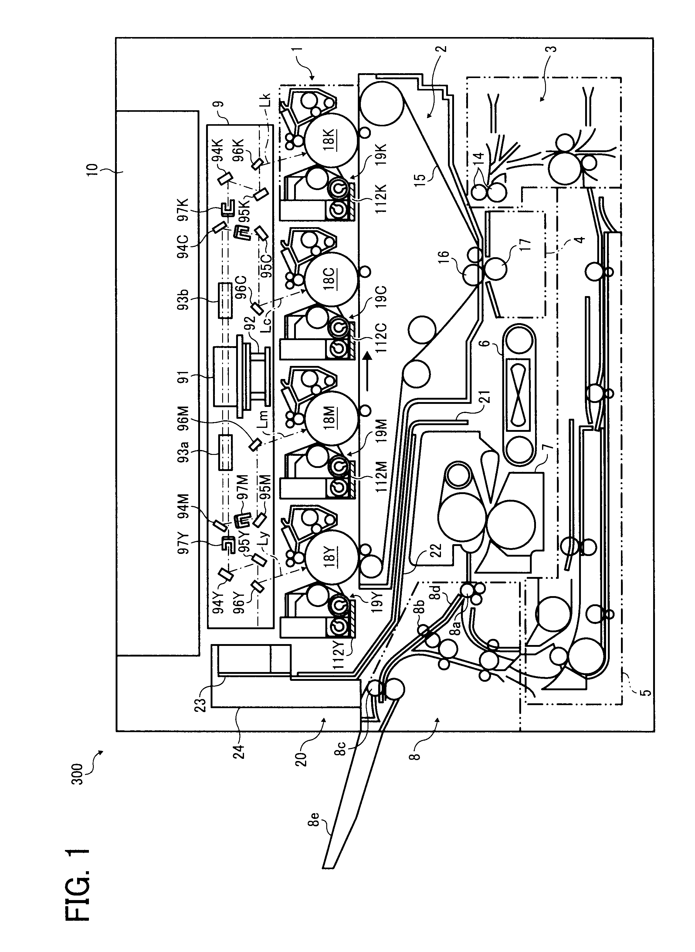
[0034]Referring now to the drawings, wherein like reference numerals designate identical or corresponding parts throughout the several views thereof, and particularly to FIG. 1, a multicolor image forming apparatus according to an illustrative embodiment of the present invention is described.

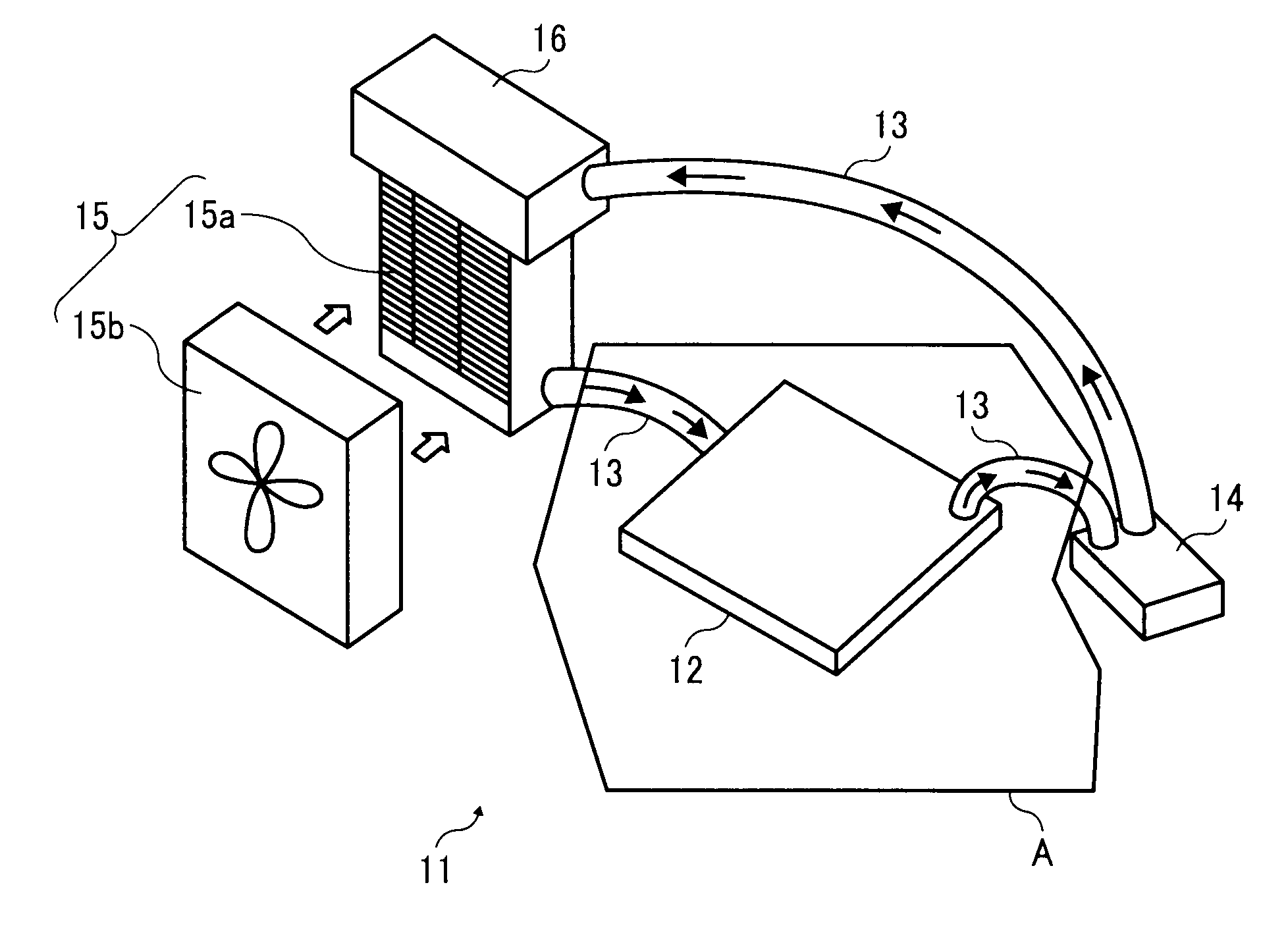
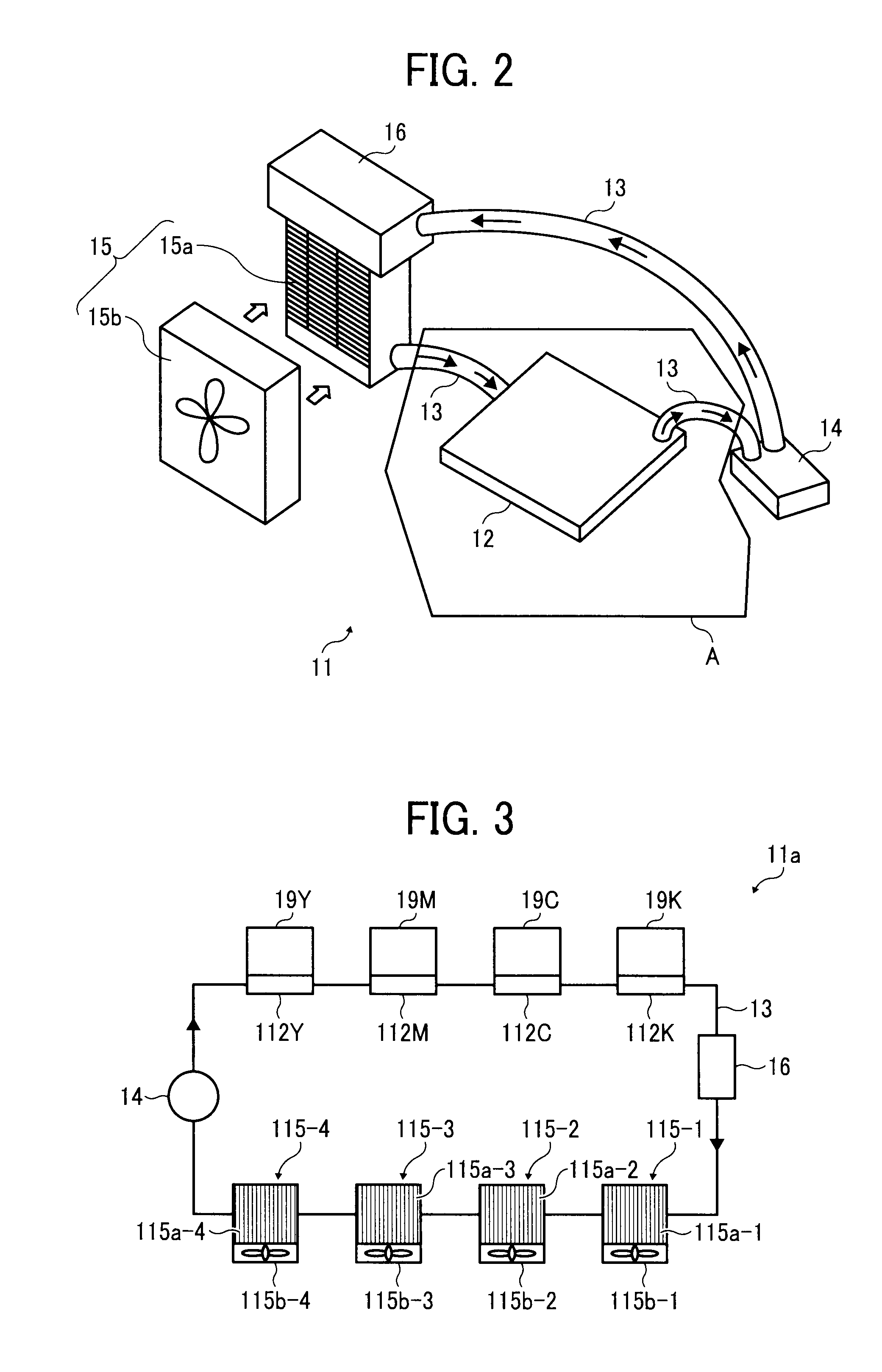
[0035]FIG. 1 is a schematic diagram illustrating a configuration of an image forming apparatus 300. As shown in FIG. 1, the image forming apparatus 300 includes an image forming unit 1 that includes photoconductors 18Y, 18M, 18C, and 18K disposed in parallel. Development devices 19Y, 19M, 19C, and 1...


PUM


Abstract

An image forming apparatus includes an image forming unit including an image carrier and a development device, a transfer unit to transfer an image formed on the image carrier onto a sheet, a fixing device to fix the image on the sheet, a sheet transport unit, a sheet stack portion, an air duct, and a first liquid-cooling device. The first liquid-cooling device includes a first heat receiving member disposed in thermal contact with a first heated portion, a first heat releaser, a first circulation pipe connecting the first heat receiving member and the first heat releaser to circulate a coolant therebetween, a first transport member to transport the coolant through the first circulation pipe, and an airflow generator to generate an airflow with external air to cool the first heat releaser. The air duct guides the air taken in by the airflow generator to a second heated portion.

Description

CROSS-REFERENCE TO RELATED APPLICATIONS[0001]This patent specification is based on and claims priority from Japanese Patent Application No. 2008-301013, filed on Nov. 26, 2008 in the Japan Patent Office, which is hereby incorporated by reference herein in its entirety.BACKGROUND OF THE INVENTION[0002]1. Field of the Invention[0003]The present invention generally relates to an image forming apparatus such as a copier, a printer, a facsimile machine, or a multifunction machine including at least two of these functions, and a method of cooling the apparatus.[0004]2. Discussion of the Background Art[0005]In general, electrophotographic image forming apparatuses, such as copiers, printers, facsimile machines, or multifunction devices including at least two of those functions, etc., include an exposure device to direct writing light onto an image carrier so as to form an electrostatic latent image thereon, a development device to develop the latent image with developer, a transfer unit to...

Claims


Application Information

Patent Timeline
IPC IPC(8): G03G21/20
CPCG03G21/206G03G2221/1645
Inventor TAKEHARA, KENICHIIIJIMA, YASUAKIFUJIYA, HIROMITSUNISHIMURA, TAKAYUKIOKANO, SATOSHIHIRASAWA, TOMOYASUSUZUKI, SHINGOSAITOH, MASANORI
Owner RICOH KK
Features
  • Generate Ideas
  • Intellectual Property
  • Life Sciences
  • Materials
  • Tech Scout
  • Unparalleled Data Quality
  • Higher Quality Content
  • 60% Fewer Hallucinations
Learn More