Metered cooling slots for turbine blades

Active Publication Date: 2010-05-27
GENERAL ELECTRIC CO
View PDF17 Cites 35 Cited by
  • Summary
  • Abstract
  • Description
  • Claims
  • Application Information

AI Technical Summary

Benefits of technology

[0006]The present application thus describes a metered cooling slot disposed in a wall comprising an outer surface that is exposed to a hot gas stream flowing in a downstream direction and an inner surface that defines a portion of an internal coolant chamber through which a coolant passes, the metered cooling slot comprising: a slot formed within the outer surface elongated in a first direction, the slot comprising a pair of spaced apart, opposing, slot surfaces and a base, the slot surfaces intersecting the outer surface at a shallow angle to form a slot outlet opposite the base; and two or more metering apertures formed within the wall, each metering aperture intersecting the inner surface of the wall to form a metering aperture inlet and intersecting one of the pair of slot surfaces to form a metering aperture outlet, the metering aperture being oriented to direct the coolant against the opposite slot surface at a steep angle; wherein: D represents the approximate diameter of at least two of the metering apertures; P represents the approximate distance between the center lines of at least two neighboring metering apertures; and P/D comprises a value within the range of about 4 to 6.
[0007]The present application further describes a metered cooling slot disposed in a wall comprising an outer surface that is exposed to a hot gas stream flowing in a downstream direction and an inner surface that defines a portion of an internal coolant chamber through which a coolant passes, the

Problems solved by technology

While this shortcoming may be cured somewhat by increasing the amount of cooling air released, it is well known in the art that the usage of bypass cooling air should be limited due to its negative impact on efficiency.
That is, whenever possible, the use of cooling air should be minimized because such cooling air is working fluid which has been extracted from the compressor and its loss from the gas flow path rapidly reduces engine e

Method used


Image

  • Metered cooling slots for turbine blades
  • Metered cooling slots for turbine blades
  • Metered cooling slots for turbine blades

Examples


Embodiment Construction

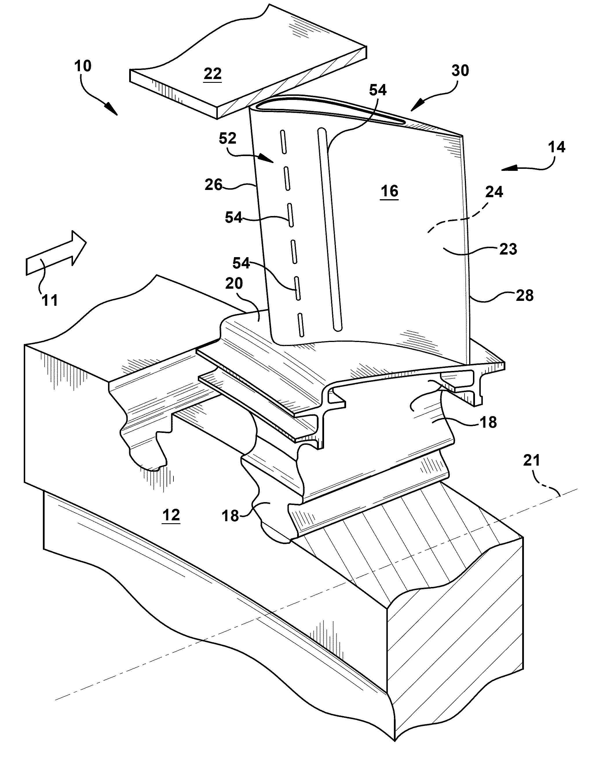
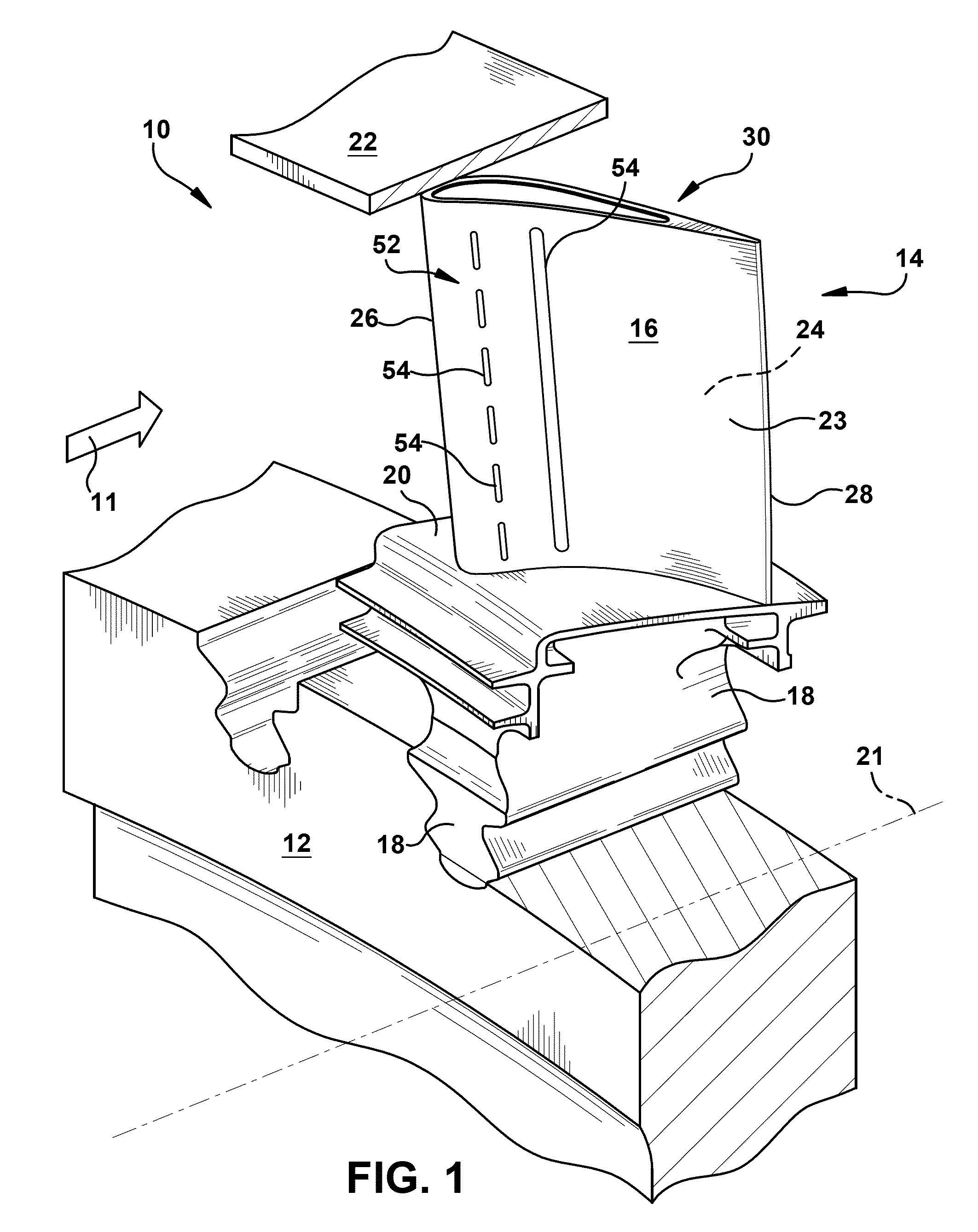
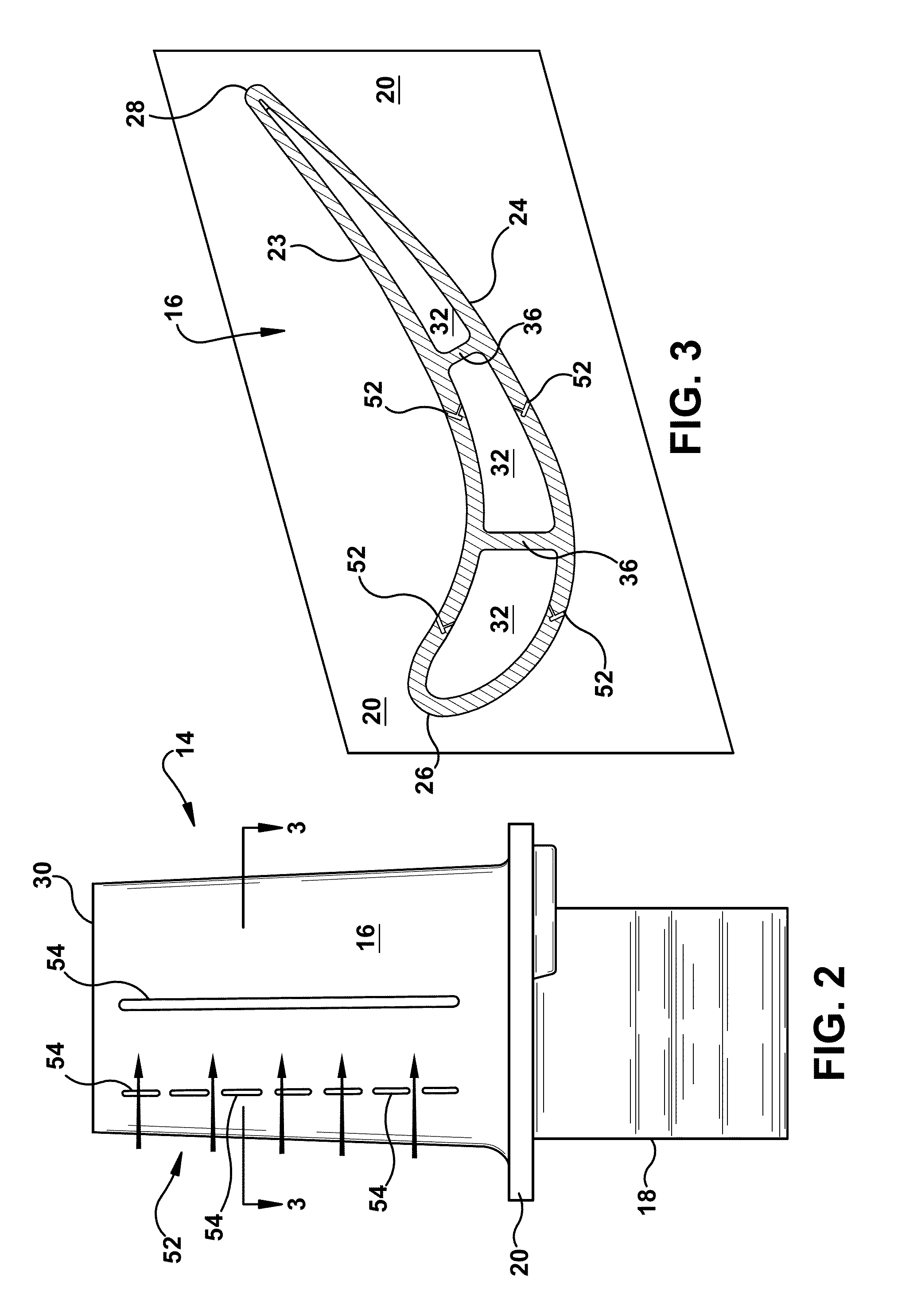
[0018]Referring now to the drawings, wherein identical numerals indicate the same elements throughout the figures, FIG. 1 depicts a turbine assembly 10 of a gas turbine engine. The turbine assembly 10 is mounted directly downstream from a combustor (not shown) for receiving hot combustion gases 11 therefrom. The turbine assembly 10 generally comprises a disk 12 having a plurality of rotor blades 14 securely attached thereto. Typically, the rotor blade 14 comprises a hollow airfoil 16 that extends radially from a root 18, which it generally is integral therewith. A platform 20 is disposed at the base of the airfoil 16 and generally is also integral therewith. The turbine assembly 10 is axisymmetrical about an axial centerline axis 21. An annular shroud 22 surrounds the blades 14 and is suitably joined to a stationary stator casing (not shown). The shroud 22 provides a relatively small clearance or gap between it and the rotor blades 14, which limits the leakage of combustion gases 11...


PUM


Abstract

A metered cooling slot disposed in a wall comprising an outer surface that is exposed to a hot gas stream and an inner surface that defines an internal coolant chamber through which a coolant passes, the metered cooling slot comprising: a slot formed within the outer surface elongated in a first direction, the slot comprising a pair of spaced apart, opposing, slot surfaces and a base, the slot surfaces intersecting the outer surface to form a slot outlet opposite the base; and two or more metering apertures formed within the wall, each metering aperture intersecting the inner surface of the wall to form a metering aperture inlet and intersecting one of the pair of slot surfaces to form a metering aperture outlet; wherein: D represents the approximate diameter of at least two of the metering apertures; P represents the approximate distance between the center lines of at least two neighboring metering apertures; and P/D comprises a value within the range of about 4 to 6.

Description

BACKGROUND OF THE INVENTION[0001]This present application relates generally to apparatus, methods and / or systems for improving film cooling of components in gas turbine engines. More specifically, but not by way of limitation, the present application relates to apparatus, methods and / or systems pertaining to film cooling slots with metered flow.[0002]Gas turbine engines typically include a compressor, a combustor, and a turbine. The compressor and turbine generally include rows of blades that are axially stacked in stages. Each stage includes a row of circumferentially-spaced stator blades, which are fixed, and a row of rotor blades, which rotate about a central axis or shaft. In operation, generally, the compressor rotor blades rotate about the shaft, and, acting in concert with the stator blades, compress a flow of air. The supply of compressed air then is used in the combustor to combust a supply of fuel. The resulting flow of hot expanding gases from the combustion is expanded t...

Claims


Application Information

Patent Timeline
IPC IPC(8): F01D5/18
CPCF01D5/186F05D2260/202F01D5/187
Inventor BRITTINGHAM, ROBERT A.REED, ROBERT J.BRUCE, KEVIN L.JOHNS, DAVID R.
Owner GENERAL ELECTRIC CO
Why Eureka
Try Eureka