Non-aqueous electrolyte battery wherein a battery case and a terminal are connected through resistance

a technology of non-aqueous electrolyte and battery case, which is applied in the direction of cell components, final product manufacturing, sustainable manufacturing/processing, etc., can solve the problems of generating violent sparks, short circuits that are mistakenly shorted, and workers may be injured, so as to suppress aluminum alloying and suppress iron dissolution

Active Publication Date: 2010-05-27
GS YUASA INT LTD
View PDF7 Cites 5 Cited by
  • Summary
  • Abstract
  • Description
  • Claims
  • Application Information

AI Technical Summary

Benefits of technology

[0021]Where the battery case contains aluminum, the problem of corrosion of the battery case can be solved by connecting the battery case to the positive electrode through electron conduction. Because of this measure, even if poor insulation occurs between the battery case and the negative terminal, the potential of the battery case will not become the negative electrode potential. This suppresses alloying of aluminum of the battery case and lithium.
[0022]Where the battery case contains iron, the problem of corrosion of the battery case can be solved by connecting the battery case to the negative electrode through electron conduction. Because of this measure, even if poor insulation occurs between the battery case and the positive terminal, the potential of the battery case will not become the positive electrode potential. This suppresses dissolving of iron of the battery case into the electrolyte solution.
[0024]This invention intends to solve all these problems. Namely, this invention provides a battery which can suppress corrosion of a battery case even if poor insulation occurs between a terminal and the battery case. In addition, this invention provides a battery which is difficult to damage the battery and its peripheral components due to the generation of sparks.
[0026]In the first invention, since the positive terminal is connected to the battery case through the electron conduction, even if poor insulation occurs between the negative terminal and the battery case, the potential of the battery case will not become the negative electrode potential. Thus, corrosion of the battery case is suppressed. In addition, since the positive terminal is connected to the battery case through a resistance of 1Ω to 1 MΩ, even if the negative terminal is erroneously short-circuited with battery case, generation of violent sparks can be suppressed. As a result, damage of the battery and its peripheral components is suppressed.
[0028]In the second invention, since the negative terminal is connected to the battery case through the electron conduction, even if poor insulation occurs between the positive terminal and the battery case, the potential of the battery case will not become the positive electrode potential. Thus, corrosion of the battery case is suppressed. In addition, since the negative terminal is connected to the battery case through a resistance of 1Ω to 1 MΩ, even if the positive terminal is erroneously short-circuited with battery case, generation of violent sparks can be suppressed. As a result, damage of the battery and its peripheral components is suppressed.

Problems solved by technology

The non-aqueous electrolyte secondary battery is involved in two problems that it may be erroneously short-circuited when batteries are connected in series or in parallel to make a composite battery and short-circuited during use for a long time.
Owing to this short-circuiting, a current of several thousands amperes flows through the contact area to generate violent sparks.
As a result, a worker may be injured and the battery may be broken.
Where the non-aqueous electrolyte secondary battery is used for a long time, water in the air and conductive granules may be applied to the insulator between the terminal and metallic battery case, thereby deteriorating the insulation.

Method used


Image

  • Non-aqueous electrolyte battery wherein a  battery case and a terminal are connected through resistance
  • Non-aqueous electrolyte battery wherein a  battery case and a terminal are connected through resistance
  • Non-aqueous electrolyte battery wherein a  battery case and a terminal are connected through resistance

Examples


examples

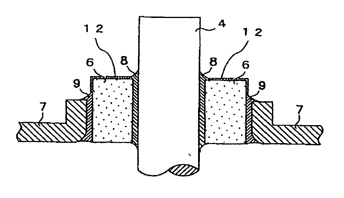
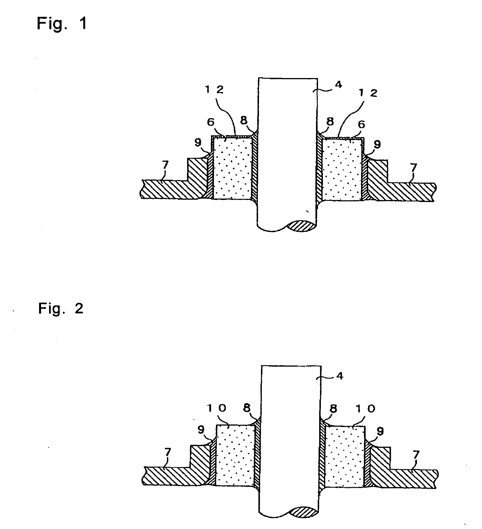
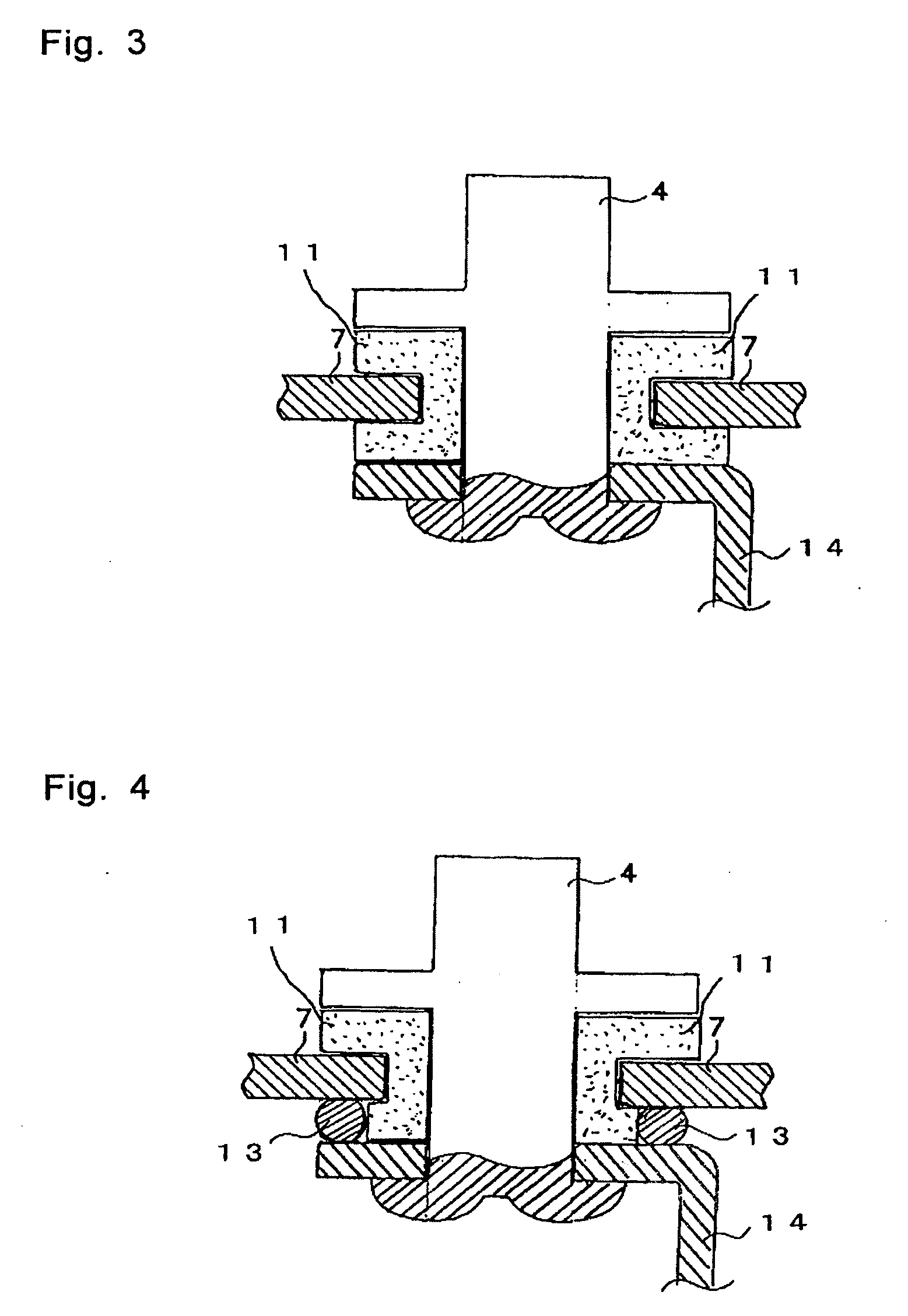
[0038]Referring to the drawings, an explanation will be given of the mode for carrying out this invention.

example 2

[0044]The non-aqueous electrolyte secondary battery according to Example 2 was manufactured in the same manner as in Example 1 except that the quantity of carbon of the carbon-doped polyamide resin applied to the battery outer surface of the insulating cylinder of the positive terminal is adjusted to provide a resistance of 10 kΩ between the positive terminal and battery case in the battery before the electrolyte solution is injected.

example 3

[0045]The non-aqueous electrolyte secondary battery according to Example 3 was manufactured in the same manner as in Example 1 except that the quantity of carbon of the carbon-doped polyamide resin applied to the battery outer surface of the insulating cylinder of the positive terminal is adjusted to provide a resistance of 100Ω between the positive terminal and battery case in the battery before the electrolyte solution is injected.


PUM

PropertyMeasurementUnit
resistanceaaaaaaaaaa
shapesaaaaaaaaaa

Abstract

A non-aqueous electrolyte battery comprising: a battery case containing aluminum; a positive electrode terminal attached to the battery case; and a negative electrode terminal attached to the battery case and insulated from the battery case, wherein the positive electrode terminal and the battery case are connected through a resistor having resistance of 1Ω to 1 MΩ. Otherwise, A non-aqueous electrolyte battery comprising: a battery case containing iron; a negative electrode terminal attached to the battery case; and a positive electrode terminal attached to the battery case and insulated from the battery case, wherein the negative electrode terminal and the battery case are connected through a resistor having resistance of 1Ω to 1 MΩ.

Description

[0001]This application is a Divisional of application Ser. No. 11 / 002,178 filed Dec. 3, 2004, which claims priority from Japanese Patent Application No. 2003-407181 filed Dec. 5, 2003. The entire disclosures of the prior applications are hereby incorporated by reference.FIELD OF THE INVENTION[0002]This invention relates to a non-aqueous electrolyte battery having a positive electrode terminal and a negative terminal which are fixed to a battery case.BACKGROUND ART[0003]There are some kinds of the non-aqueous electrolyte secondary battery using a metallic battery case. There are the following three typical shapes. The first shape is a shape in which a positive electrode terminal (hereinafter simply referred to a positive terminal) and a negative electrode terminal (hereinafter referred to as a negative terminal) are both insulated from a metallic case. The second shape is a shape in which the negative terminal is insulated from the metallic case serving as the positive terminal. The ...

Claims


Application Information

Patent Timeline
Patent Type & Authority Applications(United States)
IPC IPC(8): H01M2/30H01M4/131H01M6/10H01M10/05H01M10/058H01M50/119H01M50/528H01M50/559H01M50/564
CPCH01M2/0285H01M2/06H01M2/26Y02E60/12H01M6/10H01M10/0525H01M2/30H01M2/342Y02E60/10H01M50/597Y02P70/50H01M50/559H01M50/564H01M50/119
Inventor ISHII, TETSUYA
Owner GS YUASA INT LTD
Why Eureka
Try Eureka