Catalyst for exhaust gas purification

A technology of exhaust gas purification and catalyst, applied in the direction of physical/chemical process catalyst, catalyst activation/preparation, heterogeneous catalyst chemical elements, etc., can solve the problem of oxygen absorption efficiency reduction

Active Publication Date: 2016-08-24
TOYOTA JIDOSHA KK
View PDF8 Cites 0 Cited by
  • Summary
  • Abstract
  • Description
  • Claims
  • Application Information

AI Technical Summary

Problems solved by technology

However, these low noble metal exhaust gas purification catalysts have low content of noble metals mediating oxygen absorption, and thus the efficiency of oxygen absorption into the OSC support is ultimately greatly reduced

Method used


Image

  • Catalyst for exhaust gas purification
  • Catalyst for exhaust gas purification
  • Catalyst for exhaust gas purification

Examples


example 1

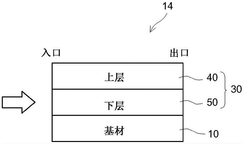
[0072] A catalyst for exhaust gas purification in which Rh was arranged in the upper layer and Pd was arranged only in the lower layer was manufactured in Example 1.

[0073] (1) Formation of the lower layer

[0074] By adding 75g / L alumina (Al 2 o 3 ) powder was suspended in the nitric acid type Pd reagent solution containing 0.82g / L Pd to prepare a dispersion. Mix the following into this dispersion to obtain a slurry: CeO 2 -ZrO 2 Composite oxide OSC material powder (CeO 2 : 30% by weight, ZrO 2 : 60% by weight, Y 2 o 3 : 5% by weight, La 2 o 3 : 5% by weight), 5% by weight barium acetate, 5% by weight Al 2 o 3 binder, and distilled water. The slurry was dried at 120° C. for 30 minutes and calcined at 500° C. for 2 hours to obtain a catalyst material for the lower layer.

[0075] Then, this lower layer catalyst material was dispersed in an acidic aqueous solution to prepare a lower layer forming slurry (A). Using this underlayer-forming slurry (A), washcoating ...

example 2~5

[0082] Catalysts for purifying exhaust gas in which Rh was arranged in the upper layer and Pd was arranged in both the upper layer and the lower layer were prepared in Examples 2 to 5. Specifically, a certain amount of catalyst material for a lower layer is subtracted from the above-mentioned slurry (A) for forming a lower layer and the same amount of catalyst material for a lower layer is mixed into the slurry (B) for forming an upper layer. A front stage upper layer forming slurry (C) was prepared as in Example 1. Proceeding as in Example 1, these three slurries (A), (B) and (C) were washed-coated on a substrate and dried and calcined to produce a catalyst for exhaust gas purification. This production was performed so as to provide Pd amounts of 0.04 g, 0.08 g, 0.16 g, and 0.24 g in the entire upper layer in the order of Examples 2 to 5, respectively. The amount of Pd in ​​the entire catalyst was kept constant at 0.65 g.

example 6

[0084] A catalyst for purification of exhaust gas in which Rh was arranged in the upper layer and Pd was arranged in both the upper layer and the lower layer was produced in Example 6. However, in this example, Pd in ​​the upper layer was disposed therein without being supported on the carrier. Specifically, a certain amount of Pd (without support) was subtracted from the above-mentioned lower layer-forming slurry (A) and the same amount of Pd (without support) was mixed into the upper layer-forming slurry (B). A front stage upper layer forming slurry (C) was prepared as in Example 1. Proceeding as in Example 1, these three slurries (A), (B) and (C) were washed on the substrate and dried and calcined to prepare a catalyst for exhaust gas purification. This production was performed so as to provide a Pd amount of 0.16 g in the entire upper layer.

[0085] For the catalysts for exhaust gas purification according to Examples 1 to 6, given in Table 1 below: the amount of Pd in ​...


PUM


Abstract

An exhaust gas purification catalyst is provided with a substrate and a catalyst coating layer formed on the surface of the substrate. The catalyst coating layer is formed into a layered structure having upper and lower layers, with a lower layer being closer to the surface of the substrate and an upper layer being relatively farther therefrom. The catalyst coating layer is provided with Rh and Pd as precious metal catalysts and is provided with an OSC material having an oxygen storage capacity as a support. The Rh is disposed in the upper layer of the catalyst coating layer, and the Pd is disposed in both the upper layer and the lower layer of the catalyst coating layer. At least a portion of the Pd in the upper layer and in the lower layer is supported on the OSC material. The mass ratio of the Pd disposed in the upper layer to the Pd disposed in the lower layer is not more than 0.4.

Description

technical field [0001] The present invention relates to an exhaust gas purifying catalyst for purifying exhaust gas exhausted from an internal combustion engine. [0002] This international application claims priority from Japanese Patent Application No. 2011-288798 filed on December 28, 2011, the entire contents of which are hereby incorporated by reference. Background technique [0003] Three-way catalysts containing at least one noble metal selected from platinum (Pt), palladium (Pd) and rhodium (Rh) are generally used to purify exhaust gas from internal combustion engines such as automobile engines (Patent Documents 1 to 3). In a typical three-way catalyst structure, a catalyst coating made of alumina is formed on the surface of a highly heat-resistant ceramic substrate and at least one noble metal selected from Pd, Pt, and Rh is supported on the catalyst coating middle. Among these noble metals, Pd and Pt mainly contribute to the purification ability of carbon monoxid...

Claims


Application Information

Patent Timeline
Patent Type & Authority Patents(China)
IPC IPC(8): B01D53/94B01J37/02B01J23/00B01J23/63B01J23/83B01J23/89B01J35/04
CPCB01D53/945B01D2255/1023B01D2255/1025B01D2255/2061B01D2255/2065B01D2255/9022B01D2255/908B01J23/002B01J23/44B01J23/464B01J23/63B01J35/0006B01J37/0201B01J37/0244B01J37/038B01J2523/00Y02T10/12B01J2523/25B01J2523/36B01J2523/3706B01J2523/3712B01J2523/48B01J2523/3725B01J2523/3718
Inventor 青木悠生
Owner TOYOTA JIDOSHA KK
Why Eureka
Try Eureka