Power transmission device

power technology, applied in the direction of electric variable regulation, process and machine control, instruments, etc., can solve the problems of complex circuit configuration of each device, difficult to employ a power transmission device for transmitting electric power to a general power receiving device, and abnormal heating

Active Publication Date: 2010-06-03
CASIO COMPUTER CO LTD
View PDF4 Cites 27 Cited by
  • Summary
  • Abstract
  • Description
  • Claims
  • Application Information

AI Technical Summary

Benefits of technology

[0012]It is, therefore, a main object of the present invention to provide a power transmission device that can determine whether or riot electric power is being transmitted to a power receiving device only by control operations in the power transmission device.

Problems solved by technology

In the power transmission device, when power transmission is started under the condition that a metallic foreign material is present, the transmitted electric power is absorbed by the metallic foreign material, which causes abnormal heating.
In order to send and receive signals between a primary device and a secondary device, a circuit configuration of each device is complicated.
Further, because it is necessary to provide each of the primary device and secondary device with a corresponding circuit or coil for sending and receiving signals, it is difficult to employ a power transmission device for transmitting electric power to a general power receiving device.

Method used


Image

  • Power transmission device
  • Power transmission device
  • Power transmission device

Examples


Embodiment Construction

[0022]An embodiment of the present invention will be described below with reference to the drawings.

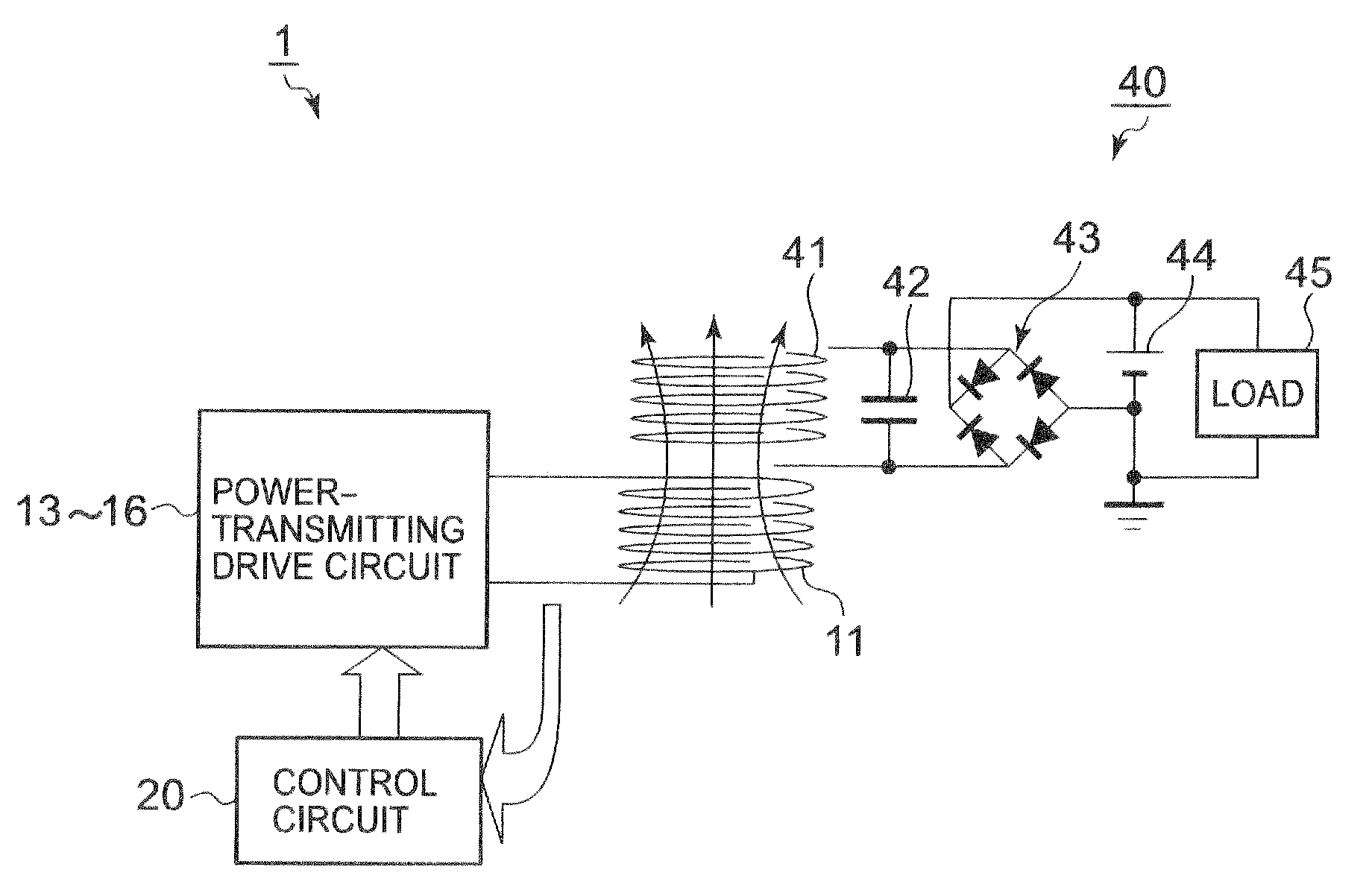
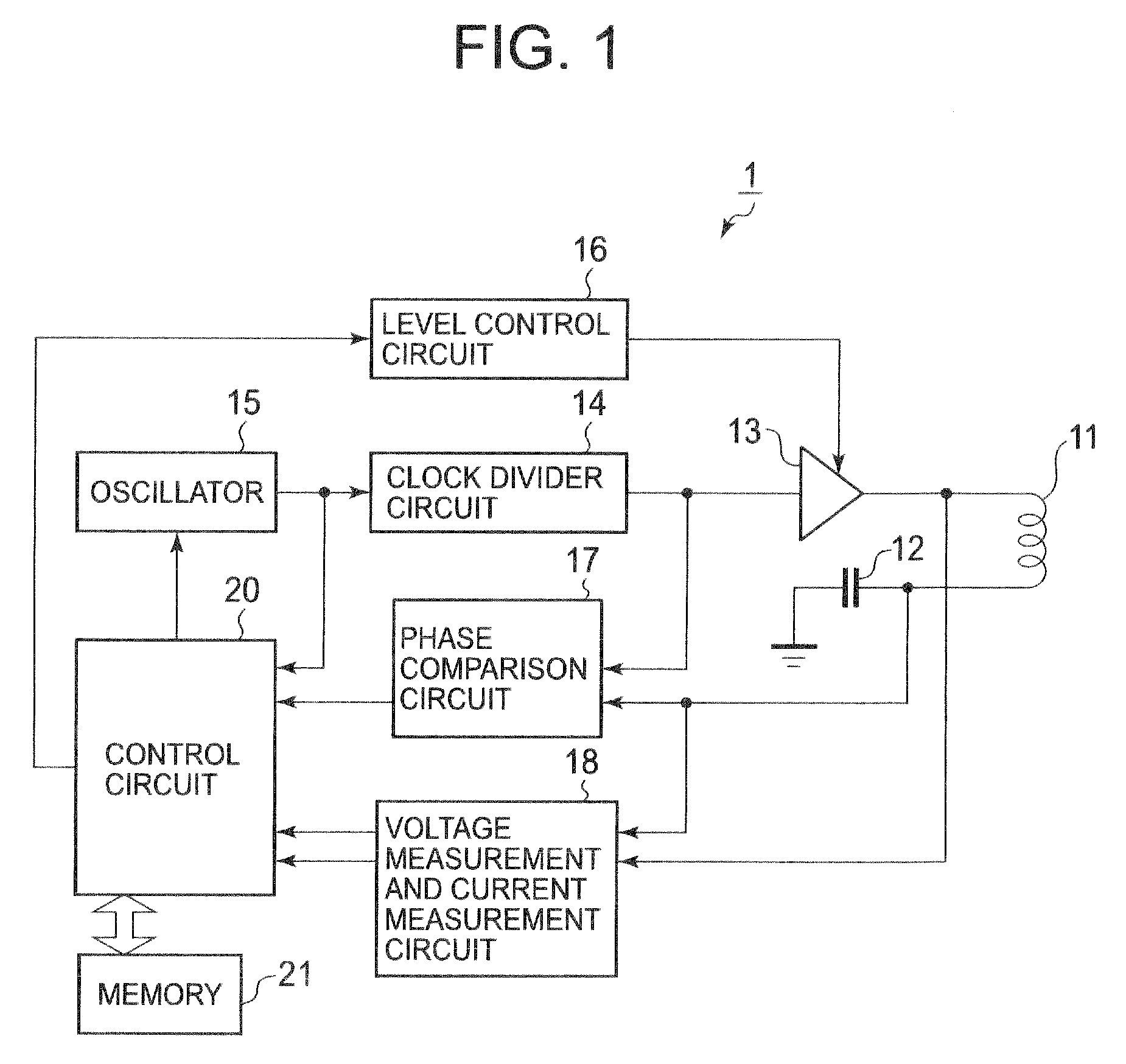
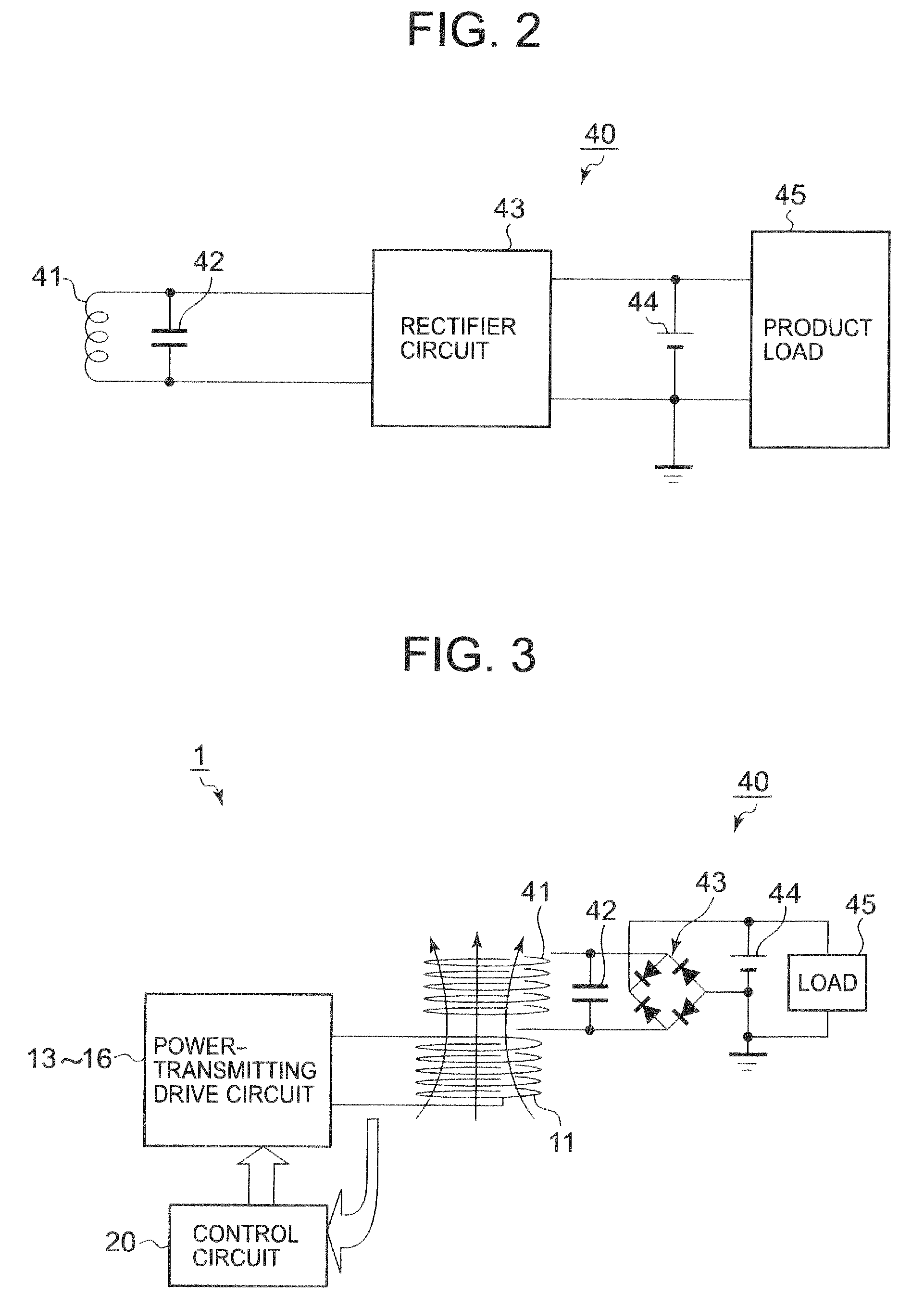
[0023]FIG. 1 is a block diagram showing a circuit configuration of a power transmission device according to an embodiment of the present invention. FIG. 2 is a block diagram showing an exemplary circuit configuration of a power receiving device.

[0024]A power transmission device 1 of this embodiment transmits power in a wireless manner using an electromagnetic induction method to a power receiving device 40. As shown in FIG. 1, the power transmission device 1 includes a power transmission coil 11 that performs power transmission using an electromagnetic induction method, a resonant capacitor 12 that is connected in series to the power transmission coil 11, a drive circuit 13 as a driving unit that drives the power transmission coil 11, a clock divider circuit 14 and an oscillator 15 that supply a control signal for periodic driving the drive circuit 13, a level control circuit 16 that ...


PUM


Abstract

A power transmission device includes: a power transmission coil to transmit electric power to a power receiving coil by an electromagnetic induction method; driving unit to supply a driving voltage to the power transmission coil; a detection unit to detect an electric current flowing in the power transmission coil based on the driving voltage; a control unit to change an amplitude of the driving voltage; a starting point detection unit to detect the amplitude of the driving voltage as a characteristic point at which an electric current starts to flow in the power receiving coil, on a characteristic line representing a relationship between the driving voltage supplied to the power transmission coil and the electric current detected by the detection unit; and a transmission stopping control unit to stop power transmission by the power transmission coil if the characteristic point is not detected by the starting point detection unit.

Description

CROSS-REFERENCE TO RELATED APPLICATIONS[0001]This application is based upon and claims benefit of priority from the prior Japanese Patent Application No. 2008-307087, filed on Dec. 2, 2008, and the entire contents of which are incorporated herein by reference.BACKGROUND OF THE INVENTION[0002]1. Field of the Invention[0003]The present invention relates to a power transmission device that transmits electric power to a power receiving device by an electromagnetic induction method.[0004]2. Description of Related Art[0005]A power transmission device that transmits electric power to a secondary device in a non-contact manner by an electromagnetic induction method is already known.[0006]In the power transmission device, when power transmission is started under the condition that a metallic foreign material is present, the transmitted electric power is absorbed by the metallic foreign material, which causes abnormal heating.[0007]Therefore, in a technique for transmitting a certain amount o...

Claims


Application Information

Patent Timeline
Patent Type & Authority Applications(United States)
IPC IPC(8): H02J17/00H03K3/53
CPCH02J7/025H02J50/12H02J50/60H02J7/00034H02J7/00
Inventor SEKINO, SHIGEOSOMEYA, KAORU
Owner CASIO COMPUTER CO LTD
Why Eureka
Try Eureka