Reactive power regulation and voltage support for renewable energy plants

a renewable energy and power supply technology, applied in the field of power regulation, can solve the problems of failure to address the short-term voltage regulation of the power source or compensate for the reactive power loss of transmission lines

Active Publication Date: 2010-06-03
GENERAL ELECTRIC CO
View PDF9 Cites 58 Cited by
  • Summary
  • Abstract
  • Description
  • Claims
  • Application Information

AI Technical Summary

Benefits of technology

[0006]According to an exemplary embodiment of the invention, a method for coordinating voltage and reactive power output of a plant, including one or more power sources, with one or more requirements associated with a utility is provided. The method can include generating a VAR regulator output signal based at least in part on a reactive power control signal received from a utility, controlling reactive power and voltage output of the one or more power sources based at least in part on the generated VAR regulator output signal, aggregating reactive power output or the one or more power sources, and providing the aggregated reactive power to the utility.
[0007]According to another exemplary embodiment, a system for coordinating voltage and reactive power output of one or more power sources with one or more requirements associated with a utility is provided. The system can include one or more power sources. The system may include a reactive power controller that can include a reactive power regulator operable to receive a reactive power control signal from the utility, and generate a VAR regulator output signal voltage reference based at least in part on the reactive power control signal. The reactive power controller can also include a voltage regulator operable to receive the VAR regulator output signal voltage reference generated by the reactive power regulator, receive a voltage reference from the utility, and adjust the reactive power output of the one or more power sources in response to the VAR regulator output signal voltage reference received from the reactive power regulator or the voltage reference received from the utility. The system can also include an aggregator to sum the real and reactive power output from the one or more power sources and a transmission device to transmit aggregated real and reactive power to the utility.
[0008]According to another exemplary embodiment, an apparatus for coordinating voltage and reactive power output of one or more power sources with one or more requirements associated with a utility is provided. The apparatus can include a reactive power controller. The reactive power controller can include a reactive power regulator operable to receive a reactive power control signal from the utility and generate a VAR regulator output signal voltage reference based at least in part on the reactive power control signal. The apparatus can also include a voltage regulator operable to receive the VAR regulator output signal voltage reference generated by the reactive power regulator, receive a voltage reference from the utility, and adjust the reactive power output of the one or more power sources in response to the VAR regulator output signal voltage reference received from the reactive power regulator or the voltage reference received from the utility. The apparatus may also include an aggregator to sum the real and reactive power output from the one or more power sources.

Problems solved by technology

Such methods and systems may fulfill demand and stabilize the electrical grid by generating reactive power but fail to address the short-term regulation of voltage from the power source or compensate for reactive power loss in transmission lines.

Method used


Image

  • Reactive power regulation and voltage support for renewable energy plants
  • Reactive power regulation and voltage support for renewable energy plants
  • Reactive power regulation and voltage support for renewable energy plants

Examples


Embodiment Construction

[0014]Embodiments of the invention will be described more fully hereinafter with reference to the accompanying drawings, in which embodiments of the invention are shown. This invention may, however, be embodied in many different forms and should not be construed as limited to the embodiments set forth herein; rather, these embodiments are provided so that this disclosure will be thorough and complete, and will fully convey the scope of the invention to those skilled in the art. Like numbers refer to like elements throughout.

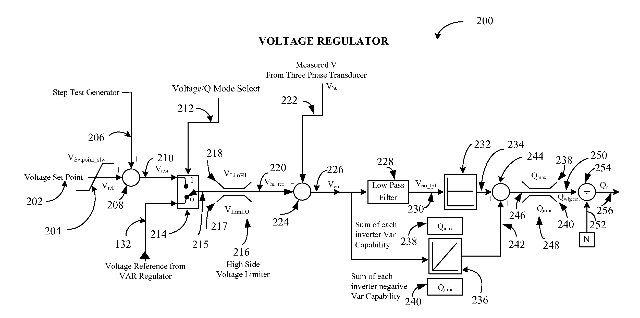
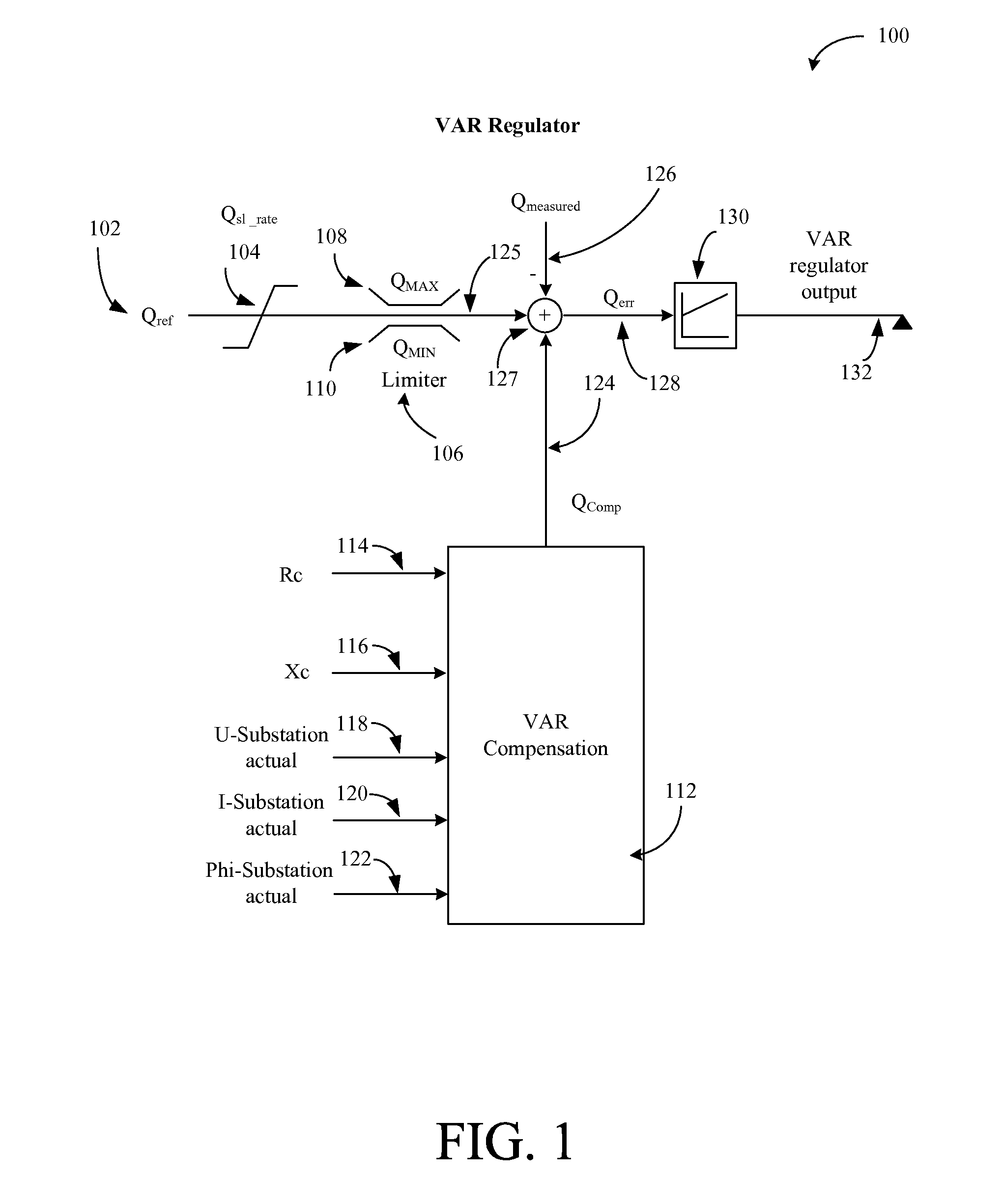
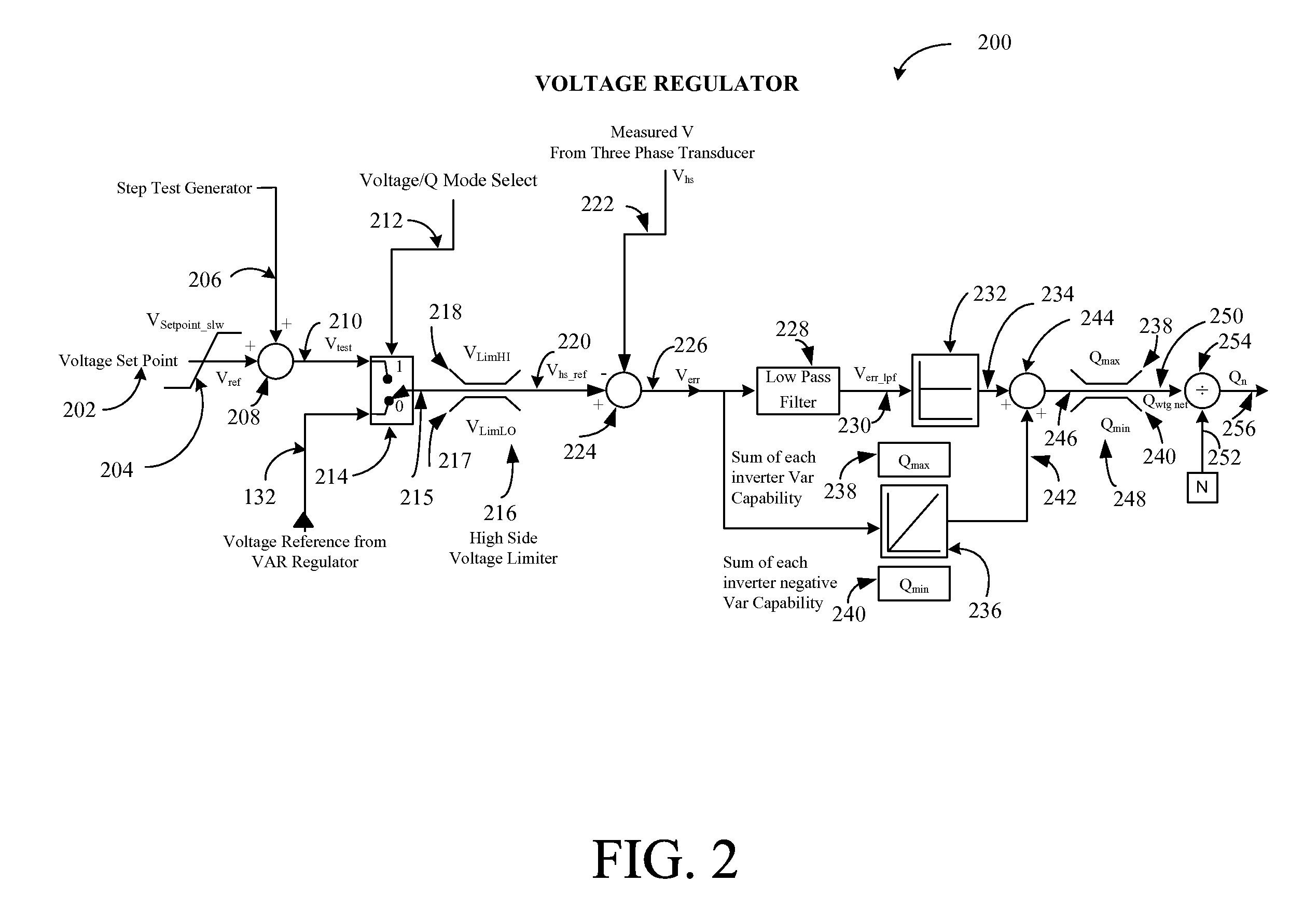
[0015]Certain embodiments of the invention can coordinate the reactive power and voltage from a variable output renewable power plant with the requirements of a utility. For example, the watt output of a renewable source power plant may vary with different operating conditions (e.g. wind turbine speed, cloud coverage, etc.), and certain embodiments of the invention can maintain the proper amount of voltage regulation and VAR (volt-amp reactive) support. The VARs ...


PUM


Abstract

Systems and methods are provided for reactive power regulation and voltage support for renewable energy plants. In one embodiment, a system and method are provided for coordinating voltage and reactive power output of a plant with one or more requirements associated with a utility. The method can include generating a VAR regulator output signal based at least in part on a reactive power control signal received from a utility, controlling reactive power and voltage output of the one or more power sources based at least in part on the generated VAR regulator output signal, aggregating reactive power output or the one or more power sources, and providing the aggregated reactive power to the utility.

Description

FIELD OF THE INVENTION[0001]This invention generally relates to power regulation, and more particularly relates to reactive power regulation and voltage support for renewable energy plants.BACKGROUND OF THE INVENTION[0002]Renewable energy sources, such as solar and wind farms, are becoming more economically viable as traditional fossil fuel prices continue to rise. Existing electrical power distribution (grid) infrastructure can be utilized for distributing power from renewable energy sources if the proper control system is in place for coordinating power produced with the demand of the utility. Demand for power can be measured and the demand signal can be used to control the amount of power supplied to the electrical grid by the renewable source.[0003]Real power is generated or consumed when voltage and current are in phase. Reactive power is generated or consumed with when voltage and current are 90 degrees out of phase. A purely capacitive or purely inductive load will generally ...

Claims


Application Information

Patent Timeline
Patent Type & Authority Applications(United States)
IPC IPC(8): G05F1/70
CPCG05F1/70H02J3/1821H02J3/383Y02E40/34Y02E10/563Y02E10/763H02J3/16H02J3/386H02J2300/28H02J2300/24H02J3/381Y02E10/56H02J3/50Y02E10/76Y02E40/30
Inventor CARDINAL, MARK EDWARDLARSEN, EINAR V.
Owner GENERAL ELECTRIC CO
Why Eureka
Try Eureka