Optical image stabilizer for camera lens assembly

a technology camera lens, which is applied in the field of optical image stabilizer for camera lens assembly, can solve the problems of image blurring, serious impediment to high-quality images, and increase the need to correct for movement or vibration

Active Publication Date: 2010-06-03
SAMSUNG ELECTRONICS CO LTD
View PDF30 Cites 23 Cited by
  • Summary
  • Abstract
  • Description
  • Claims
  • Application Information

AI Technical Summary

Benefits of technology

[0011]The present invention is designed to address at least the problems and / or disadvantages described above and to provide at least the advantages described below. Accordingly, an aspect of the present invention is to provide an optical image stabilizer for a camera lens assembly, which can be embedded in a small-size and lightweight photographing device such as a super compact digital camera or a mobile communication terminal that enables the photographing device to capture a clear image even when the photographing device vibrates due to handshaking.
[0012]Another aspect of the present invention provides an optical image stabilizer for a camera lens assembly, which has a simple structure, is easy to control, and reduces its manufacturing cost by making it possible to rotate the entire camera lens assembly using a piezoelectric actuator with respect to X and Y axes and moving the camera lens assembly according to handshaking of a user.
[0013]Still another aspect of the present invention provides an optical image stabilizer for a camera lens assembly, which can ensure solidity and reliability of a product while facilitating miniaturization of the product.

Problems solved by technology

As the mobility of a camera lens assembly mounted in a mobile communication terminal increases, image blurring caused by fine vibrations or handshaking represents a serious impediment to high quality images.
Moreover, frequent photographing during movement increases a need to correct for movement or vibration such as hand-shaking.
However, adjustment using a program requires a separate memory or a high-performance camera device.
The extent to which an afterimage is removed using a program is limited, resulting in degradation of a correction rate.
In the optical image stabilizer, installation of a separate correction device increases a manufacturing cost and requires additional installation space.
However, there is a limit in using the correction technique for small digital cameras or mobile communication terminals having space constraints.
As a result, the hand-shaking correction device is difficult to mount on a mobile communication terminal, where the length and outer diameter of a camera lens assembly are extremely limited.
Moreover, a difficulty in designing a small-size driving device and a raise in the manufacturing cost caused by an increase in the number of parts impede the cost competitiveness of a photographing device having the hand-shaking correction device embedded therein.
In a contact driving device such as a piezoelectric element using frictional force with its driving axis, it is difficult to control the tolerance of a contact face and secure reliability due to malfunction resulting from abrasion of the contact face.
A driving circuit for generating and applying a specific voltage waveform is required to drive the driving device such as a piezoelectric element, thus further increasing the manufacturing cost and imposing a limitation on the miniaturization of a photographing device.

Method used


Image

  • Optical image stabilizer for camera lens assembly
  • Optical image stabilizer for camera lens assembly
  • Optical image stabilizer for camera lens assembly

Examples


Embodiment Construction

[0026]Embodiments of the present invention will now be described in detail with reference to the annexed drawings. In the following description, a detailed description of known functions and configurations incorporated herein has been omitted for clarity and conciseness.

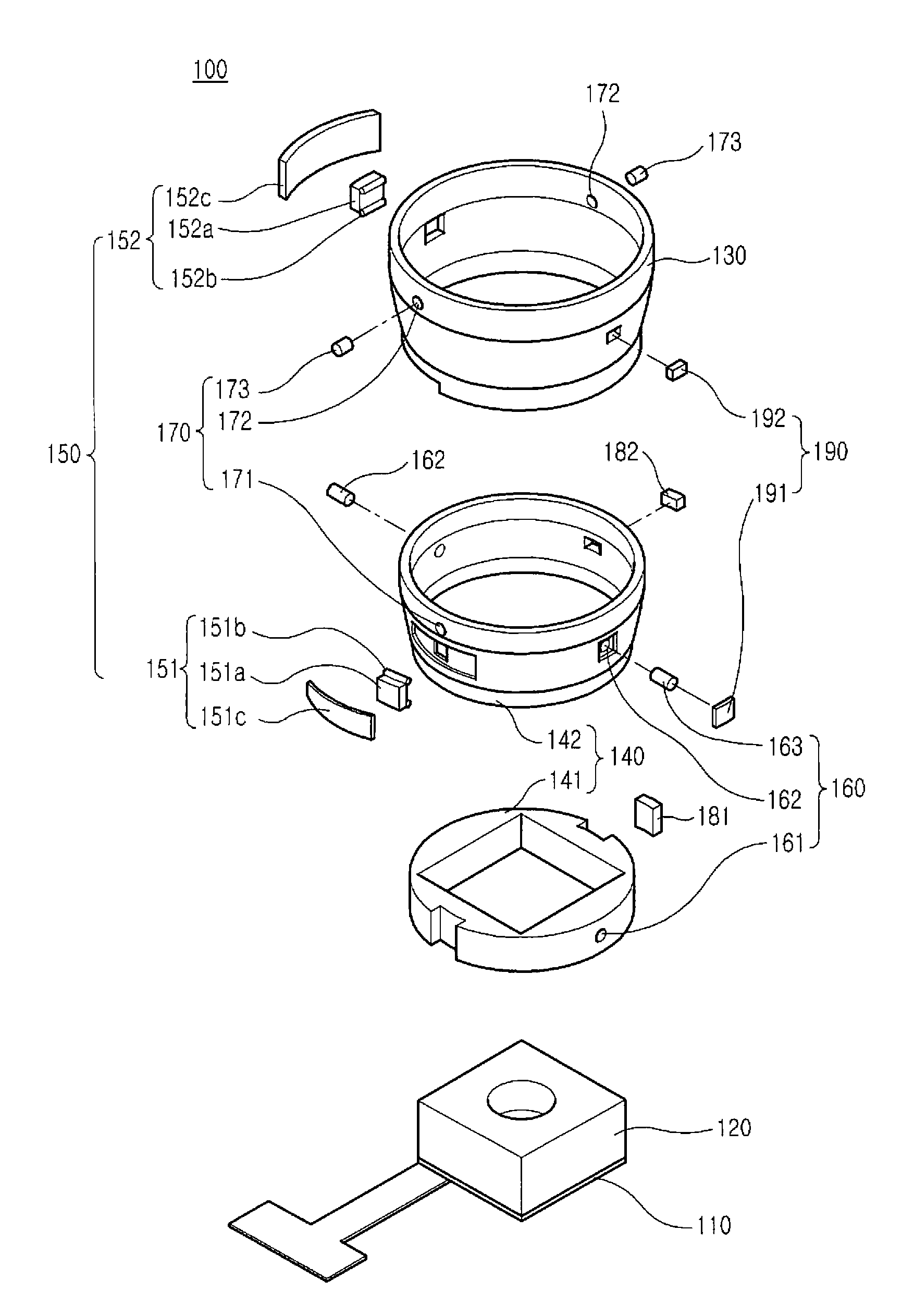
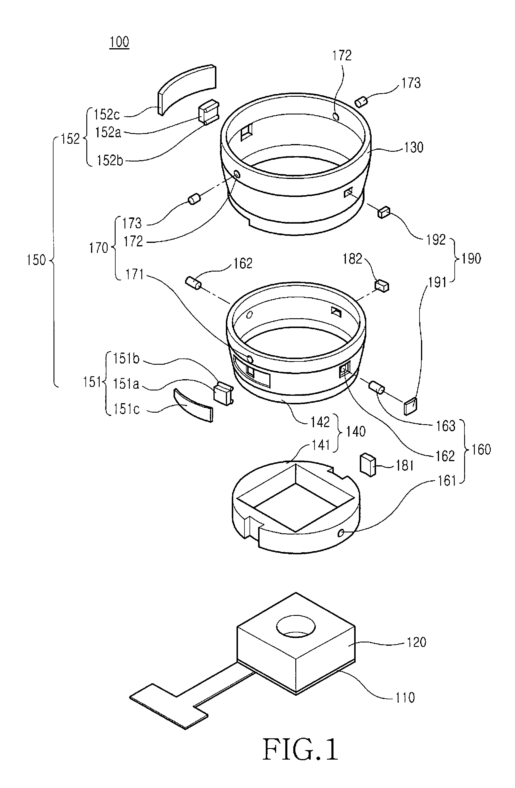
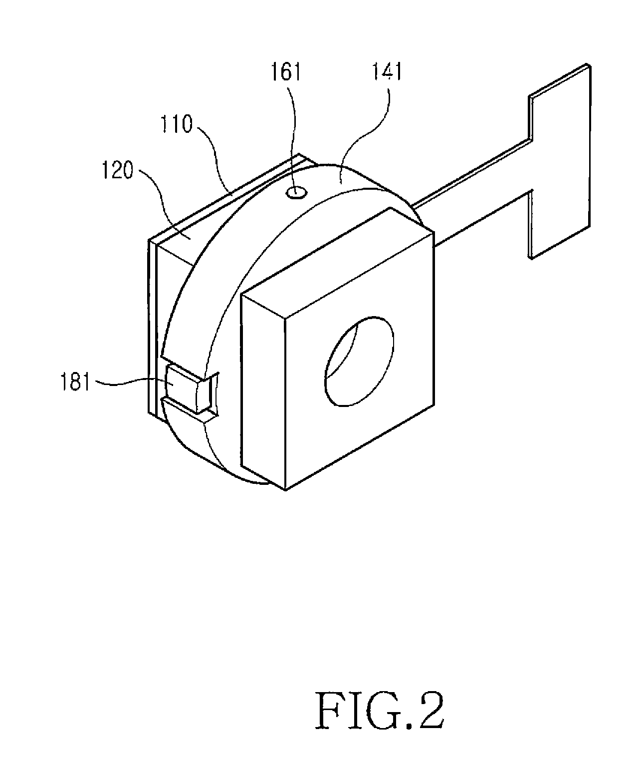
[0027]As illustrated in FIGS. 1 to 8, a camera lens assembly 100 having an optical image stabilizer includes an image sensor 110, a lens assembly 120, a housing 130, a rotator 140, and a driving member 150. The lens assembly 120 is mounted on an optical axis Z of the image sensor 110, and the housing 130 houses the lens assembly 120. The rotator 140 surrounds the lens assembly 120 to be rotatable around each of a first axis Y perpendicular to the optical axis Z and a second axis X perpendicular to the first axis Y and the optical axis Z. The rotator 140 is engaged with the lens assembly 120 and provided between the housing 130 and the lens assembly 120. The driving member 150 is provided to rotate the rotator 140 aro...


PUM


Abstract

An optical image stabilizer for correcting an image blurred by shaking of a hand while an object is photographed using a mobile communication terminal is provided. The optical image stabilizer includes an image sensor. A lens assembly is mounted on an optical axis of the image sensor. A housing contains the lens assembly. A rotator provided between the housing and the lens assembly surrounding the lens assembly rotates the lens assembly around a first axis perpendicular to the optical axis and a second axis perpendicular to the first axis in engagement with the lens assembly. A driving member rotates the rotator around the first and second axes. The optical image stabilizer can be mounted in a miniaturized lightweight photographing device, so that a clear image can be captured even during vibration of a photographing device caused by hand-shaking.

Description

PRIORITY[0001]This application claims priority under 35 U.S.C. §119(a) to a Korean Patent Application filed in the Korean Intellectual Property Office on Nov. 28, 2008 and assigned Serial No. 10-2008-120147, the contents of which are incorporated herein by reference.BACKGROUND OF THE INVENTION[0002]1. Field of the Invention[0003]The present invention relates generally to a camera lens assembly, and in particular, to an optical image stabilizer for a camera lens assembly, which corrects an image blurred by shaking of a user's hand (hereinafter, “hand-shaking”) while an object is photographed using a digital camera or an optical device mounted in a mobile communication terminal.[0004]2. Description of the Related Art[0005]With the miniaturization of digital cameras and development of lightweight techniques, the use of mobile communication terminals having optical lenses and camera devices has increased. As the mobility of a camera lens assembly mounted in a mobile communication termin...

Claims


Application Information

Patent Timeline
Patent Type & Authority Applications(United States)
IPC IPC(8): G02B27/64
CPCG02B27/646G03B5/00G03B2205/0023G03B2205/0061G02B27/64H04N23/54H04N23/6812H04N23/687
Inventor SHIN, DOO-SIK
Owner SAMSUNG ELECTRONICS CO LTD
Why Eureka
Try Eureka