Lens barrel and imaging apparatus

a technology of imaging apparatus and lens barrel, which is applied in the direction of mountings, optics, instruments, etc., can solve the problems of unsolved cost problems, inability to disclose at all the position of stop, and image disadvantageously going out of focus

Inactive Publication Date: 2010-06-03
SONY CORP
View PDF2 Cites 6 Cited by
  • Summary
  • Abstract
  • Description
  • Claims
  • Application Information

AI Technical Summary

Benefits of technology

[0019]According to the embodiments of the invention, since the coreless stepper motor, the rollers rotating in synchronization with the rotation of the stepper motor, and the intermediate ring rotating as the rollers rotate are used to drive the lens holding frame, an inexpensive, low-noise lens barrel and imaging apparatus can be provided. Further, since the rollers rotates not only in synchronization with the electrically powered rotation of the stepper motor but also in synchronization with the manual rotation of the manual ring, electrically powered automatic functions and manually operated functions are both achieved.

Problems solved by technology

Further, after the coreless motor is stopped, the position where the coreless motor has been stopped needs to be maintained in a non-energized state or a weakly energized state in order to reduce power consumption, but JP-A-59-94709 described above does not disclose at all how to hold the stop position (how to restrict the rotation of the coreless motor).
If the stop position is not held, an external force (external impact, for example) may shift the lens holding frame after an image has been brought into focus, and the image disadvantageously goes out of focus.
However, since a vibration wave motor is used to carry out the autofocus operation, the driving-related unusual noise problem and the cost problem remain unsolved.
Further, since a gear train is used to transfer the driving force and a gear member is used to switch the operation mode between the two operations, the driving noise (gear noise) problem also remains unsolved.
Moreover, JP-A-2006-259130 does not at all disclose how to hold the stop position in a non-energized state or a weakly energized state.

Method used


Image

  • Lens barrel and imaging apparatus
  • Lens barrel and imaging apparatus
  • Lens barrel and imaging apparatus

Examples


first embodiment

[Example of Cross Section of Exchangeable Lens Barrel]

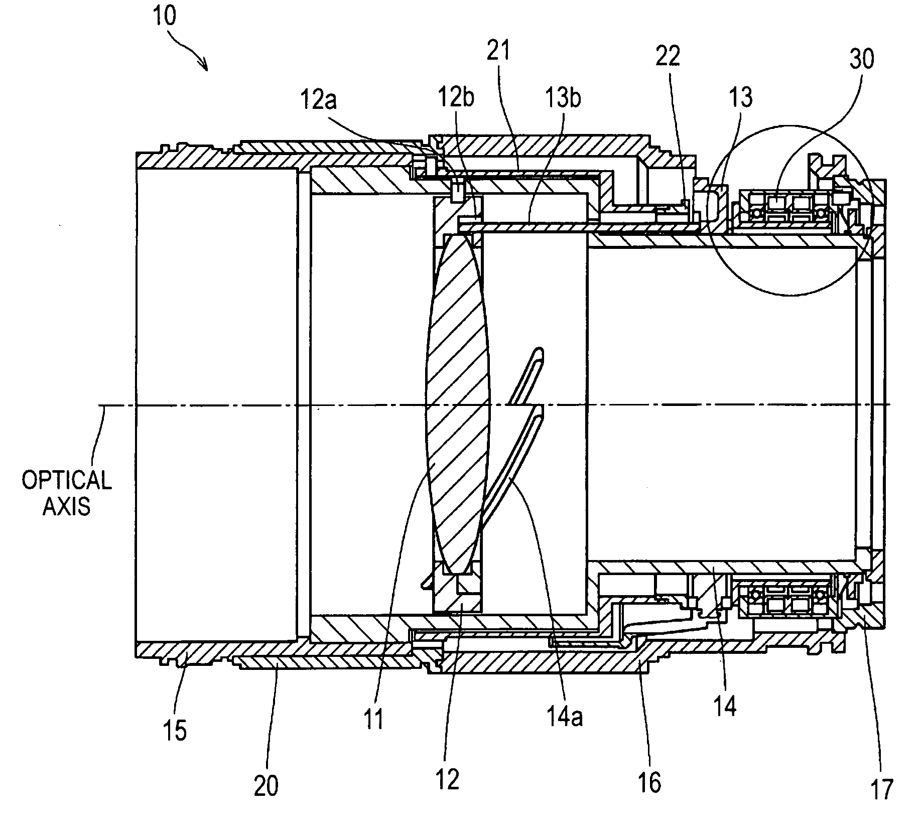
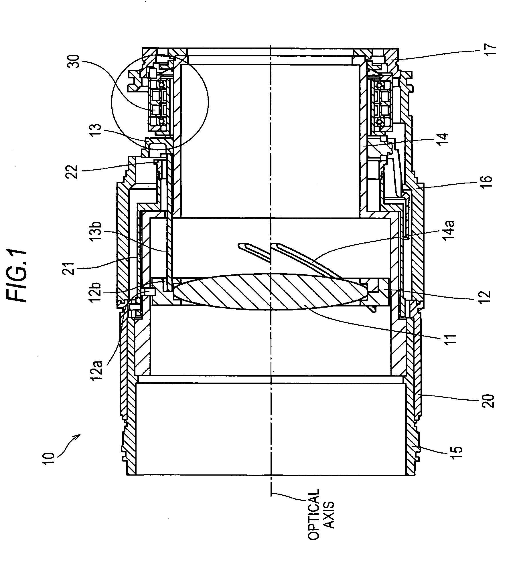
[0030]FIG. 1 is a cross-sectional view of an exchangeable lens barrel 10 taken along the optical axis, as a lens barrel according to an embodiment of the invention.

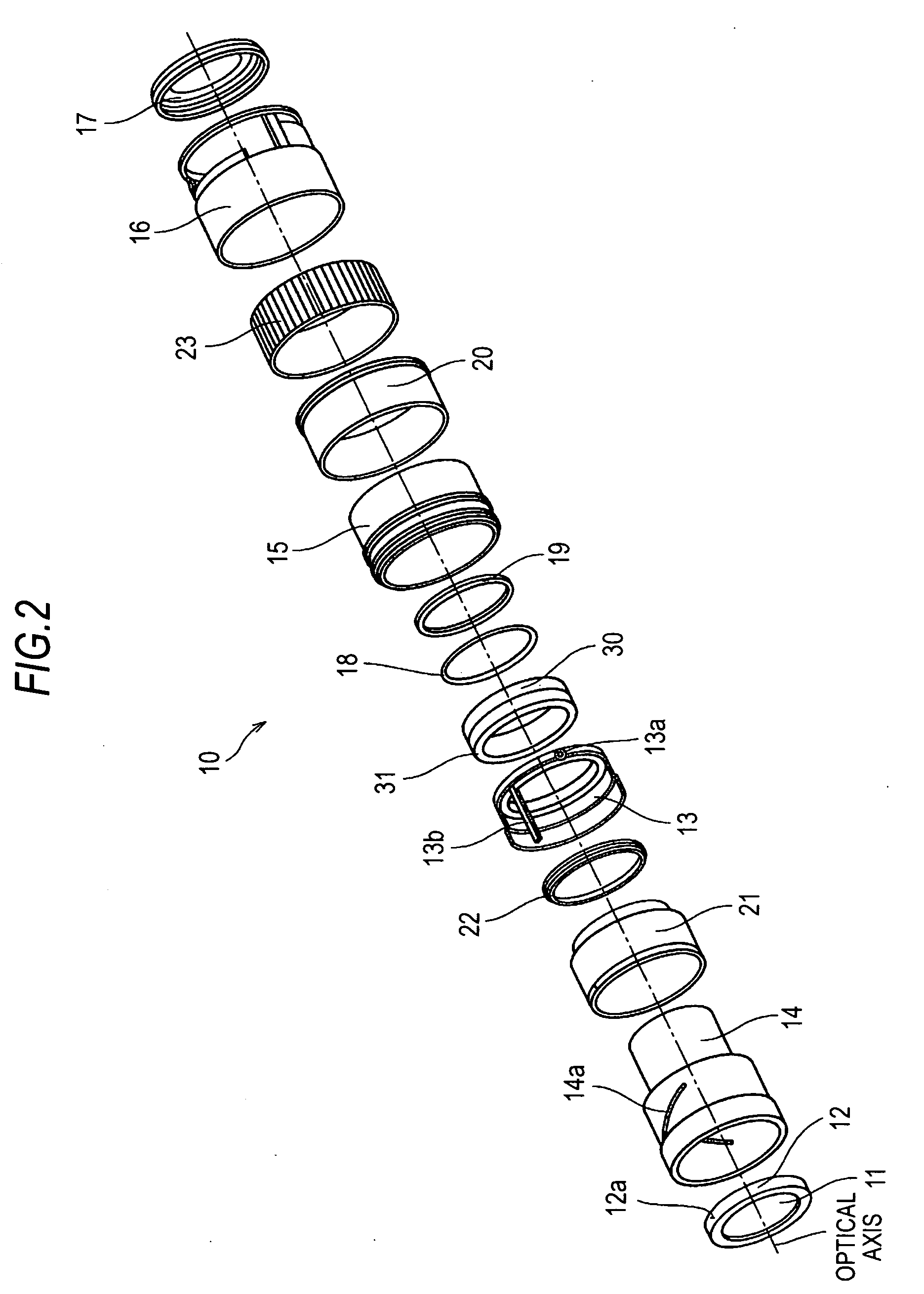
[0031]FIG. 2 is an exploded perspective view of the exchangeable lens barrel 10 shown in FIG. 1.

[0032]As shown in FIGS. 1 and 2, the exchangeable lens barrel 10 of the first embodiment includes a lens holding frame 12 that holds a lens 11 (a focus lens in the first embodiment), a manual ring 20 that is used to rotate the lens holding frame 12 manually, a coreless stepper motor 30 that electrically drives the lens holding frame 12, and a differential ring 13 (corresponding to the intermediate ring in the claims) that transfers the rotational force produced by the manual ring and the driving force produced by the stepper motor 30 to the lens holding frame 12.

[0033]The lens holding frame 12, the manual ring 20, the stepper motor 30, and the differential ring 13 are arrang...

second embodiment

2. Second Embodiment

[Example of Manual Focus Operation]

[0062]FIGS. 6A and 6B diagrammatically show an example of the manual focus operation carried out in an exchangeable lens barrel 50 (second embodiment) as a lens barrel according to an embodiment of the invention.

[0063]As shown in FIGS. 6A and 6B, the exchangeable lens barrel 50 of the second embodiment includes the same differential ring 13, rollers 13a, synchronization key 13b, manual ring 20, and stepper motor 30 as those in the exchangeable lens barrel 10 of the first embodiment shown in FIGS. 5A and 5B. The rollers 13a are rotated not only in synchronization with the rotation of the manual ring 20 but also in synchronization with the rotation of the stepper motor 30. The differential ring 13 is rotated as the rollers 13a are rotated, and the rotary motion of the differential ring 13 is transferred to the lens holding frame 12 (see FIG. 1) via the synchronization key 13b.

[0064]The exchangeable lens barrel 50 of the second em...


PUM


Abstract

A lens barrel includes: a lens holding frame holding a lens; a barrel body housing the lens holding frame; motion conversion means for converting rotary motion of the lens holding frame into reciprocating motion along the optical axis of the lens; a manual ring provided on the outer side of the barrel body and rotating around the optical axis; a coreless stepper motor provided on the outer side of the barrel body and rotating around the optical axis; rollers provided between the manual ring and the stepper motor, and rotating in synchronization with the rotation of the manual ring and the stepper motor; motor rotation preventing means for preventing the stepper motor from rotating when the rollers transfer the rotation of the manual ring; an intermediate ring rotating around the optical axis; and a transfer unit transferring the rotary motion of the intermediate ring to the lens holding frame.

Description

CROSS-REFERENCE TO RELATED APPLICATION[0001]The present application claims priority from Japanese Patent Application No. JP 2008-305301 filed in the Japanese Patent Office on Nov. 28, 2008, the entire content of which is incorporated herein by reference.BACKGROUND OF THE INVENTION[0002]1. Field of the Invention[0003]The present invention relates to a lens barrel provided in an imaging apparatus (such as a digital still camera and a digital video camcorder), a lens barrel used in an exchangeable lens, and an imaging apparatus. The present invention particularly relates to a technology for achieving automatic functions using a coreless stepper motor and manual functions that allow manual operation.[0004]2. Description of the Related Art[0005]There has been a camera including a lens barrel using an actuator to drive a lens holding frame that holds a lens. To achieve automatic functions (such as an autofocus function and an automatic zoom function) of the camera, a DC motor, an ultrason...

Claims


Application Information

Patent Timeline
Patent Type & Authority Applications(United States)
IPC IPC(8): G02B15/14G02B7/04
CPCG02B7/102
Inventor NAITOU, TSUTOMU
Owner SONY CORP
Why Eureka
Try Eureka