Method for establishing clock tracing relation and apparatus for computing clock tracing relation

a clock tracing and clock tracing technology, applied in the field of communication technologies, can solve the problems of continuous change, complex topological relationship between nodes, and breakdown of the whole network, and achieve the effects of avoiding looping, ensuring correct clock tracing and switching relation of network nodes, and optimizing the tracing path

Inactive Publication Date: 2010-06-03
HUAWEI TECH CO LTD
View PDF7 Cites 9 Cited by
  • Summary
  • Abstract
  • Description
  • Claims
  • Application Information

AI Technical Summary

Benefits of technology

[0033]In the embodiments of the present disclosure, the SPT from a root to other nodes is computed by using the clock source access node as the root; the node governed by each clock source access node is determined according to the SPT where the node resides; and a tracing path is established from the root to each end node consecutively. The source tracing relation of each node is governed and established by each relatively centralized clock source access node, without requiring mutual coordination between nodes. Therefore, the method is compatible with the centralized control of the network, and is extensible. The tracing relation is determined consecutively in the tree path so that the tracing relation is prevented from being looped and that the tracing path is optimized. Moreover, a computer-readable storage medium is provided. The computer-readable storage medium includes computer program codes which are executed by a clock source access node or another set node to ensure correctness of the clock tracing and switching relation of the network nodes.

Problems solved by technology

If the clock of a network is abnormal, service data pointer justification occurs, or even worse, the whole network breaks down.
Networks are more and more complex.
For example, in an Automatically Switched Optical Network (ASON) where a control plane is introduced, a network node generally has multiple dimensions, and the topological relation between nodes is complex and changes constantly.
Therefore, manual planning is generally not effective in ensuring correctness of the clock tracing and switching relation of the network node.

Method used


Image

  • Method for establishing clock tracing relation and apparatus for computing clock tracing relation
  • Method for establishing clock tracing relation and apparatus for computing clock tracing relation
  • Method for establishing clock tracing relation and apparatus for computing clock tracing relation

Examples


embodiment 1

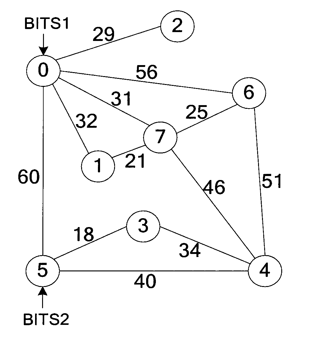
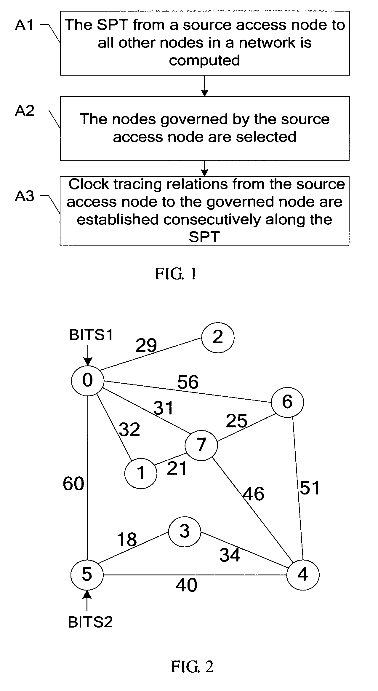
[0044] A method for establishing a clock tracing relation is provided. As shown in FIG. 1, the method includes the following steps:

[0045]A1. An SPT from a clock source access node to other nodes in a network is computed.

[0046]In this embodiment, the computation of the SPT may be a fully centralized computation. That is, the computation is undertaken by an independent network device. For example, a computation server connected to the network is responsible for computing the SPT. This independent network device responsible for computation may be regarded as a set computation node. The computation node obtains the network topology information and the clock source information to compute the SPT and select the governed node, and delivers the path information of the governed node to the corresponding clock source access node. The computation may also be partially centralized computation. That is, each clock source access node is responsible for computation. The clock source access node ob...

first embodiment

[0079]Taking a specific network such as ASON as an example, the following embodiment provides a method on the basis of the

[0080]Embodiment 2: A method for establishing a clock tracing relation in an ASON is provided. This embodiment differs from the first embodiment in that: The tracing relation is established through signaling based on the Multi-Protocol Label Switching / Generalized Multi-Protocol Label Switching (MPLS / GMPLS) protocol applied in the ASON. As shown in FIG. 6, the method includes the following steps:

[0081]B1. The SPT from a clock source access node to other nodes in a network is computed.

[0082]B2. Nodes governed by each clock source access node are selected according to the computed SPT and the clock source information corresponding to the SPT.

[0083]The foregoing two steps are similar to step A1 and step A2 in the first embodiment, and are not described further.

[0084]B3. Clock tracing relations from the clock source access node to the governed nodes are established co...

second embodiment

[0114]a tracing triggering unit 23 configured to establish clock tracing relations from the clock source access node to the governed nodes consecutively along the SPT rooted at the node of the tracing triggering unit. The tracing triggering unit 23 establishes the clock tracing relations by sending signaling to the governed nodes. For example, in an ASON, the branch end node among the governed nodes serves as a destination node, and the clock tracing relation is established by sending a PATH message that carries a specific ID. For details, the second embodiment serves as a reference.


PUM


Abstract

A method for establishing clock tracing relations and an apparatus for computing clock tracing relations are disclosed. The method includes: computing a Shortest Path Tree (SPT) from a clock source access node to other nodes in a network; selecting nodes governed by the clock source access node according to the SPT and the source information corresponding to the SPT; and establishing clock tracing relations from the clock source access node to the governed node consecutively along the SPT. The apparatus for computing clock tracing relations includes: a path computing unit, a source selecting unit, and a path issuing unit.

Description

CROSS-REFERENCE TO RELATED APPLICATIONS [0001]This application is a continuation of International Application No. PCT / CN2008 / 070984, filed on May 16, 2008, which claims priority to Chinese Patent Application No. 200710107043.X, filed with the Chinese Patent Office on May 17, 2007, both of which are hereby incorporated by reference in their entireties.FIELD OF THE TECHNOLOGY [0002]The present disclosure relates to communication technologies, and in particular, to a method for establishing clock tracing relations and an apparatus for computing clock tracing relations.TECHNICAL BACKGROUND [0003]In a communication network, the clock is vital to the quality of network services. If the clock of a network is abnormal, service data pointer justification occurs, or even worse, the whole network breaks down.[0004]Generally, the network uses one or more external clock sources to provide a clock reference for each node. Each network node traces an external clock source according to the tracing ...

Claims


Application Information

Patent Timeline
Patent Type & Authority Applications(United States)
IPC IPC(8): H04L12/28
CPCH04J3/0679H04Q2011/0079H04Q2011/0077H04Q11/0062
Inventor SHI, XINGHUAZHAO, MINFENG, JUNJIEWANG, YU
Owner HUAWEI TECH CO LTD
Why Eureka
Try Eureka