Power supply apparatus and image forming apparatus

Inactive Publication Date: 2010-06-03
CANON KK
View PDF4 Cites 14 Cited by
  • Summary
  • Abstract
  • Description
  • Claims
  • Application Information

AI Technical Summary

Benefits of technology

[0013]The present invention is directed to a power supply apparatus that enables to connect a substrate and a piezoelectric transformer using a conductive rubber, to protect the conductive rubber f

Problems solved by technology

For this purpose, insulating the electromagnetic transformer by a mold or the like is absolutely necessary, and accordingly reduction in size and reduction in weight of the power supply apparatus could not be easily realized.
Therefore, the conductive rubber will be eventually deteriorated by the surge current each time the power supply outputs a high-voltage.
Consequently, for example, like the above-described image forming apparatus, when the piezoelectri

Method used


Image

  • Power supply apparatus and image forming apparatus
  • Power supply apparatus and image forming apparatus
  • Power supply apparatus and image forming apparatus

Examples


Example

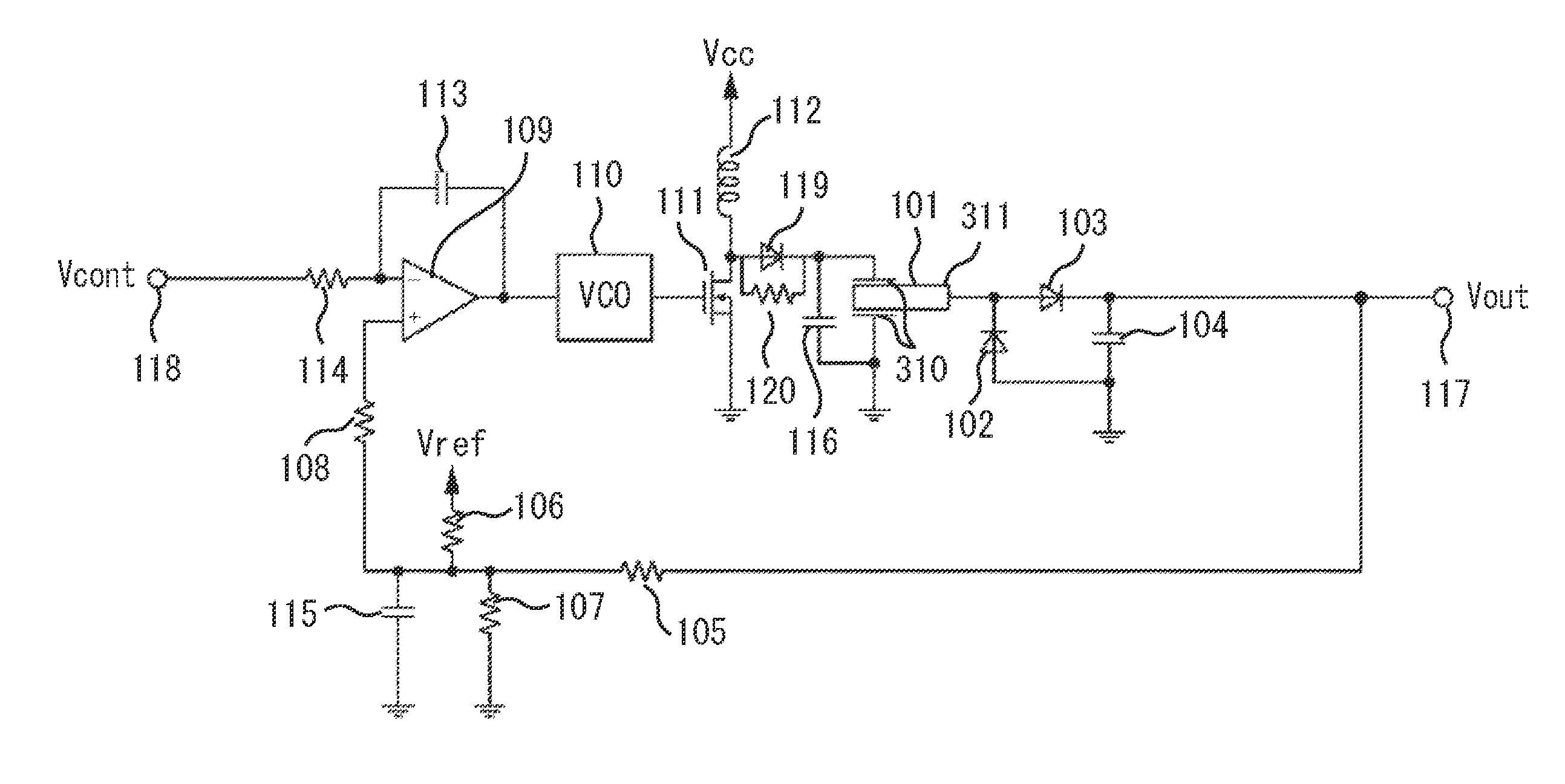
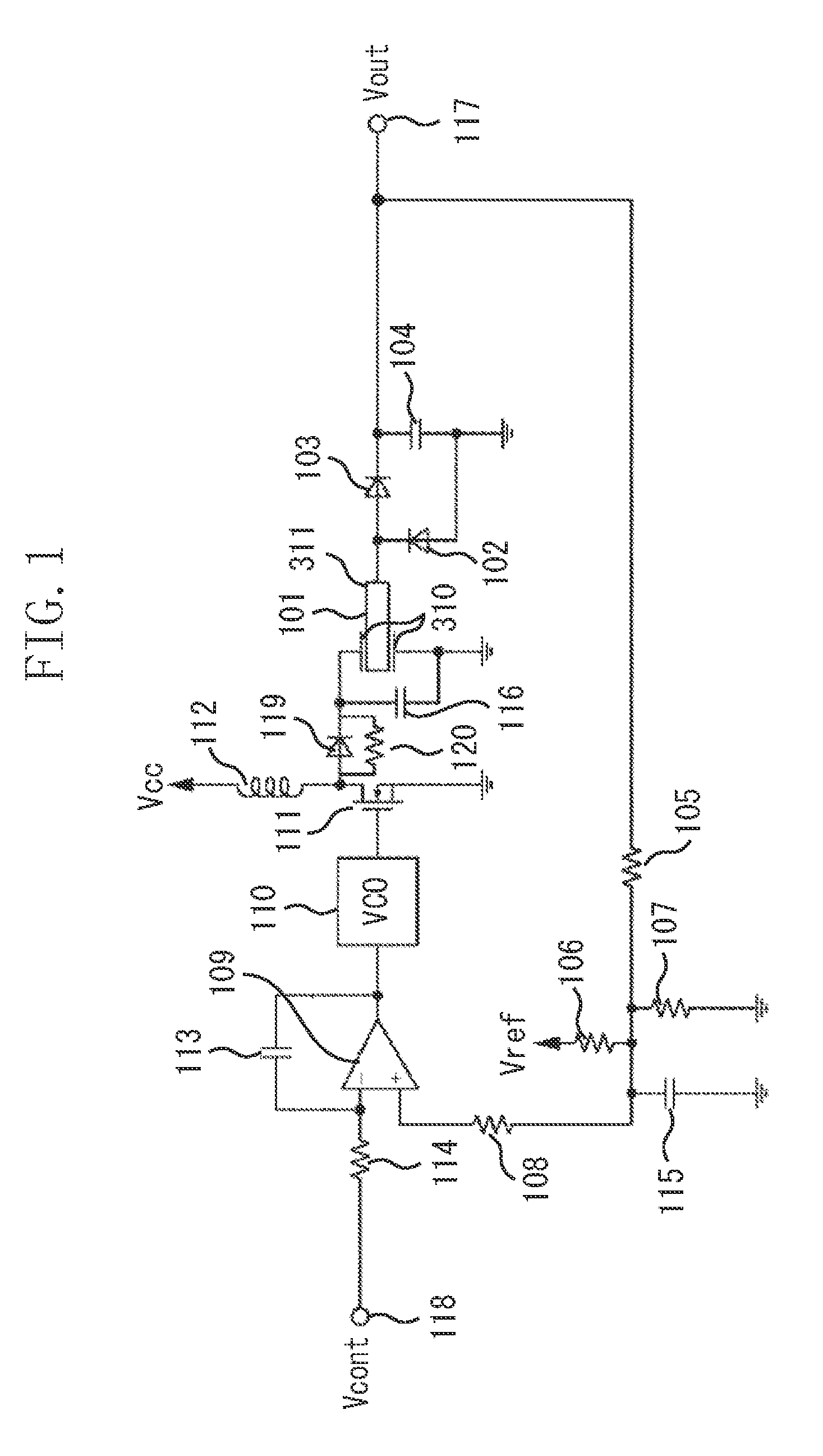
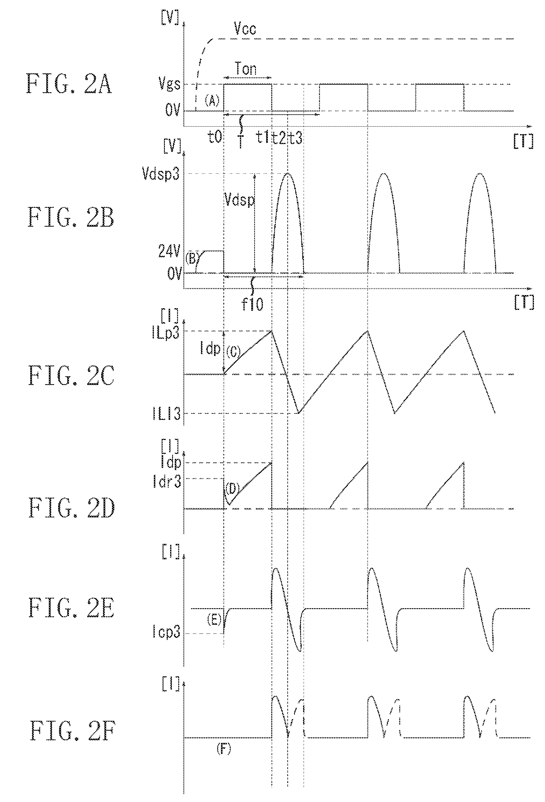
[0098]The circuit configuration described in the second exemplary embodiment is an example of variation of the circuit configuration of the first exemplary embodiment, and since the circuit operation is similar to that illustrated in the first exemplary embodiment (operation illustrated in FIG. 2), descriptions thereof will be omitted.

[0099]Further, in the present exemplary embodiment, although the FET is used for the switching element 111, the switching element 111 can be similarly operated even if a bipolar transistor is used. Further, similar to the first exemplary embodiment, the resonant capacitor 116, which is connected in parallel to the capacitance on the primary side of the piezoelectric transformer 101, works for relatively reducing an individual dispersion of the piezoelectric transformer, and making a flyback voltage in the vicinity of the resonance frequency of the piezoelectric transformer to be a desired value. If the individual dispersion of the piezoelectric transfo...


PUM


Abstract

A power supply apparatus including a current regulation unit configured to regulate a surge current generated on a primary side of a piezoelectric transformer. The surge current is generated when the piezoelectric transformer including a piezoelectric element and a holding unit, which are connected to each other using a conductive rubber, is driven.

Description

BACKGROUND OF THE INVENTION[0001]1. Field of the Invention[0002]The present invention relates to a power supply that outputs a high-voltage using a piezoelectric transformer.[0003]2. Description of the Related Art[0004]In an image forming apparatus using an electrophotographic process, an image formed on a photosensitive member (image bearing member) is transferred on a recording material thereby forming the image on the recording material. In order to transfer the image onto the recording material, the image formed on the photosensitive member is transferred to the recording material by applying a direct current (DC) high-voltage on a transfer roller (transfer member). In order to satisfactorily transfer the image formed on the photosensitive member to the recording material, it is necessary to apply a high-voltage of a several kV or over.[0005]As a power supply apparatus for such a high-voltage output, conventionally a wire-wound electromagnetic transformer has been used. However,...

Claims


Application Information

Patent Timeline
IPC IPC(8): G03G15/02H01L41/107H02M3/335
CPCG03G15/0283H02M3/335H01L41/044G03G15/80H10N30/804
Inventor NEMOTO, KENJI
Owner CANON KK
Why Eureka
Try Eureka