
Method and system for operating a wind turbine

Active Publication Date: 2010-06-03
GENERAL ELECTRIC CO
View PDF13 Cites 38 Cited by
  • Summary
  • Abstract
  • Description
  • Claims
  • Application Information

AI Technical Summary

Benefits of technology

[0006]In one embodiment, a lubrication system for a wind turbine including a control system is provided that includes a sump that is configured to collect a lubrication fluid and at least one heating unit that is configured to heat the lubrication fluid based o

Problems solved by technology

In such situations, a wind turbine may be unavailable to generate power while the lubrication oil is being heated, and significant revenue may be lost.

Method used


Image

  • Method and system for operating a wind turbine
  • Method and system for operating a wind turbine
  • Method and system for operating a wind turbine

Examples


Embodiment Construction

[0014]The embodiments described herein provide a lubrication system for a wind turbine. The lubrication system obtains one or more forecasted conditions from a wind forecast system. The lubrication system compares the forecasted conditions to one or more requirements to determine whether the wind turbine may commence or resume generating power. The lubrication system also measures a temperature of a lubrication fluid within the wind turbine. The lubrication fluid is preheated to a minimum operating temperature in advance of the arrival of the meteorological conditions that enable the wind turbine to generate power. As such, the lubrication system facilitates enabling the wind turbine to be prepared for the arrival of usable wind power.

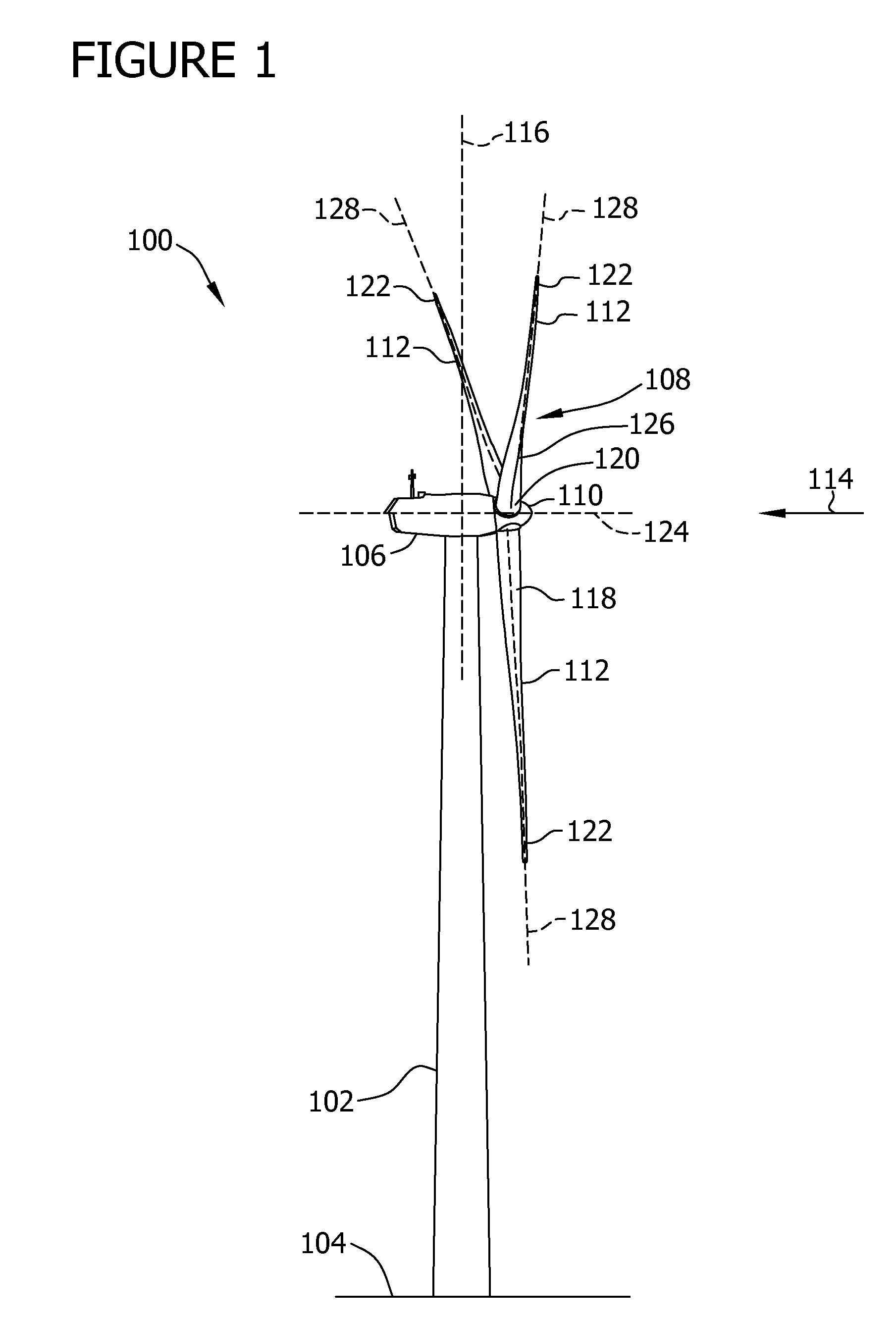
[0015]FIG. 1 is a schematic view of an exemplary wind turbine 100. In the exemplary embodiment, wind turbine 100 is a horizontal-axis wind turbine. Alternatively, wind turbine 100 may be a vertical-axis wind turbine. In the exemplary embodiment, wind t...


PUM


Abstract

A lubrication system for a wind turbine having a control system, the lubrication system including a sump configured to collect a lubrication fluid, and at least one heating unit configured to heat the lubrication fluid based on at least one forecasted condition.

Description

BACKGROUND OF THE INVENTION[0001]The subject matter described herein relates generally to wind turbines and, more particularly, to a method and system for operating a wind turbine.[0002]Wind turbines generally include a rotor having multiple blades that are attached to a rotatable hub. The rotor transforms wind energy into a rotational torque that drives one or more shafts. Often, the shafts are rotatably coupled to a gearbox that steps up the inherently low rotational speed of the rotor. The gearbox rotates a high speed shaft that drives a generator to produce electrical power, which is fed into a utility grid or to another destination.[0003]At least some known gearboxes require lubrication to function effectively. Typically, a pump transports lubrication oil to the gearbox, and a sump collects the lubrication oil after the gearbox has been lubricated. In cold environments, the lubrication oil may become viscous and resistant to flow. In such environments, one or more heaters may b...

Claims


Application Information

Patent Timeline
IPC IPC(8): F03D11/02F01M5/00
CPCF03D11/0008F05B2260/20F05B2260/98F16N2210/025F16N39/04Y02E10/722F05B2260/8211F16N7/40F03D80/70Y02E10/72
Inventor KRAUSS, THOMAS
Owner GENERAL ELECTRIC CO
Learn More