

Divided connector
a technology of connectors and connectors, applied in the direction of securing/insulating coupling contact members, coupling device connections, electric/fluid circuits, etc., can solve the problems of disadvantageous liable to occur between components and inconveniently hardly guaranteed sufficient holding strength, etc., to achieve the effect of eliminating backlash, improving positioning accuracy and terminal holding strength
- Summary
- Abstract
- Description
- Claims
- Application Information
AI Technical Summary
Benefits of technology
Problems solved by technology
Method used
Image

Examples
Embodiment Construction
[0032]Now, a preferred exemplary embodiment of a divided connector according to the present invention will be described below by referring to the drawings.
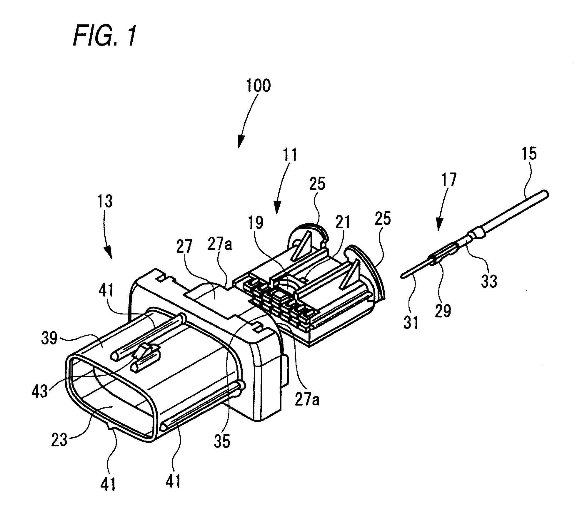
[0033]FIG. 1 is an exploded perspective view of the divided connector according to the present invention.
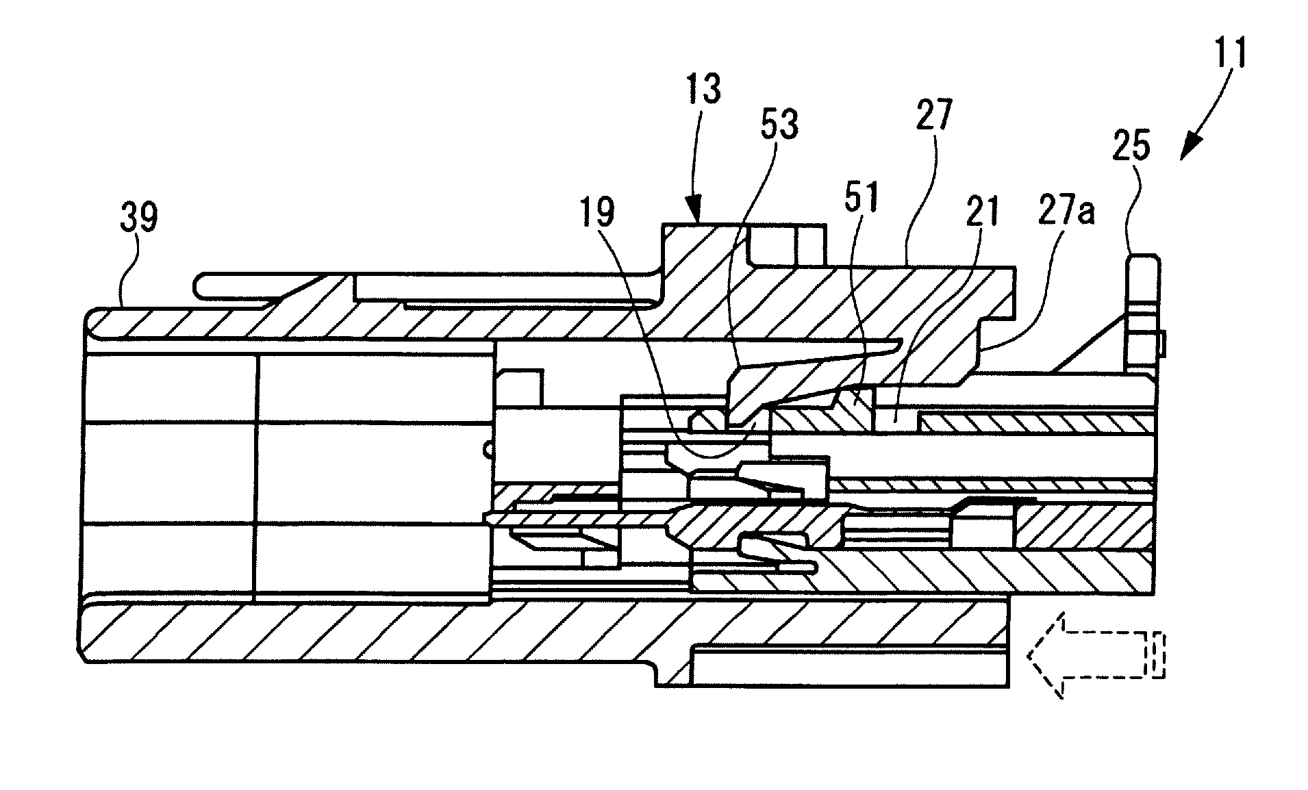
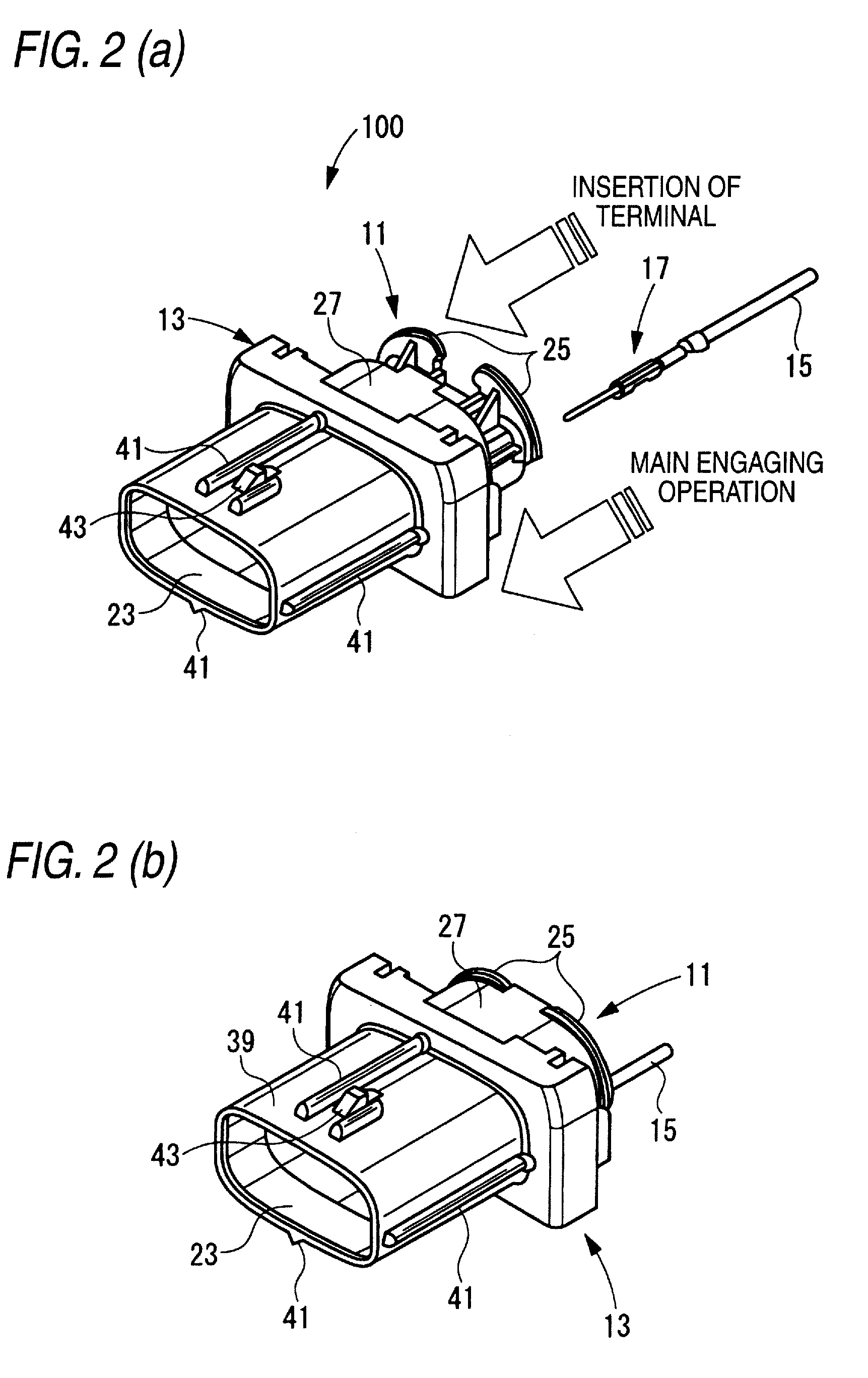
[0034]In the divided connector 100 according to the present exemplary embodiment, a housing is divided into two parts including an inner housing 11 and an outer housing 13. Namely, the front holder 507 (see FIG. 12) that has been hitherto used is removed. To the inner housing 11, a terminal 17 to which an electric wire 15 is attached under pressure is attached. The inner housing 11 to which the terminal 17 is attached is attached to the outer housing 13.
[0035]On the upper surface of the inner housing 11, are provided a temporary engaging hole 19 and a main engaging hole 21 that is provided in the rear part of the temporary engaging hole 19. In this specification, a connection opening part 23 side to a mate connector of the divi...
PUM
 Abstract
Description
Claims
Application Information