Flow rate measurement apparatus, program thereof, flow rate measurement method, and fluid supply system

a flow rate measurement and flow rate technology, applied in lighting and heating apparatus, instruments, combustion failure safes, etc., can solve problems such as uncertainty about whether a flow rate increase is necessary

Inactive Publication Date: 2010-06-03
PANASONIC CORP
View PDF8 Cites 9 Cited by
  • Summary
  • Abstract
  • Description
  • Claims
  • Application Information

AI Technical Summary

Benefits of technology

[0024]According to the present invention, a novel method for identifying an appliance, determining an operating state of the appliance, and distinguishing usage of the appliance from gas leakag...

Problems solved by technology

However, the related-art configuration encounters a problem of uncertainty about whether an increase in ...

Method used


Image

  • Flow rate measurement apparatus, program thereof, flow rate measurement method, and fluid supply system
  • Flow rate measurement apparatus, program thereof, flow rate measurement method, and fluid supply system
  • Flow rate measurement apparatus, program thereof, flow rate measurement method, and fluid supply system

Examples


Embodiment Construction

[0040]An embodiment of the present invention will hereinafter be described by reference to the drawings.

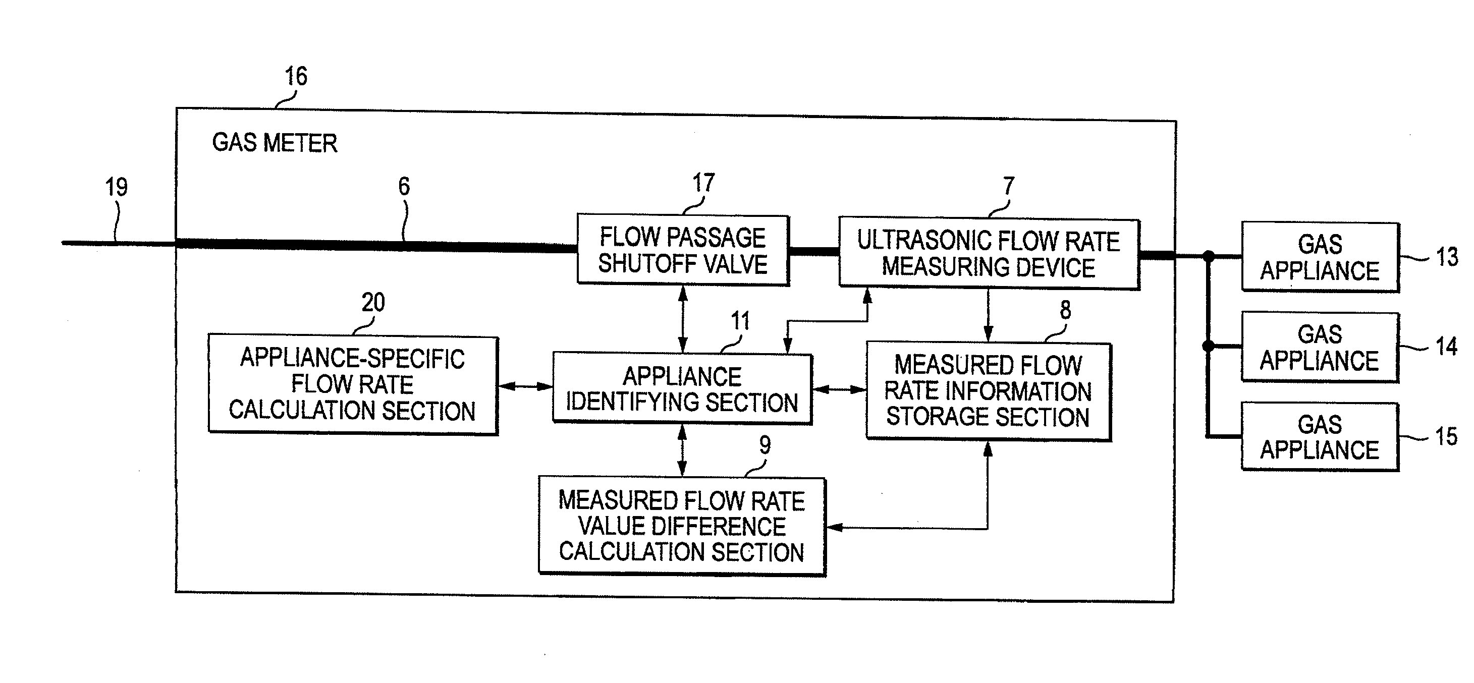
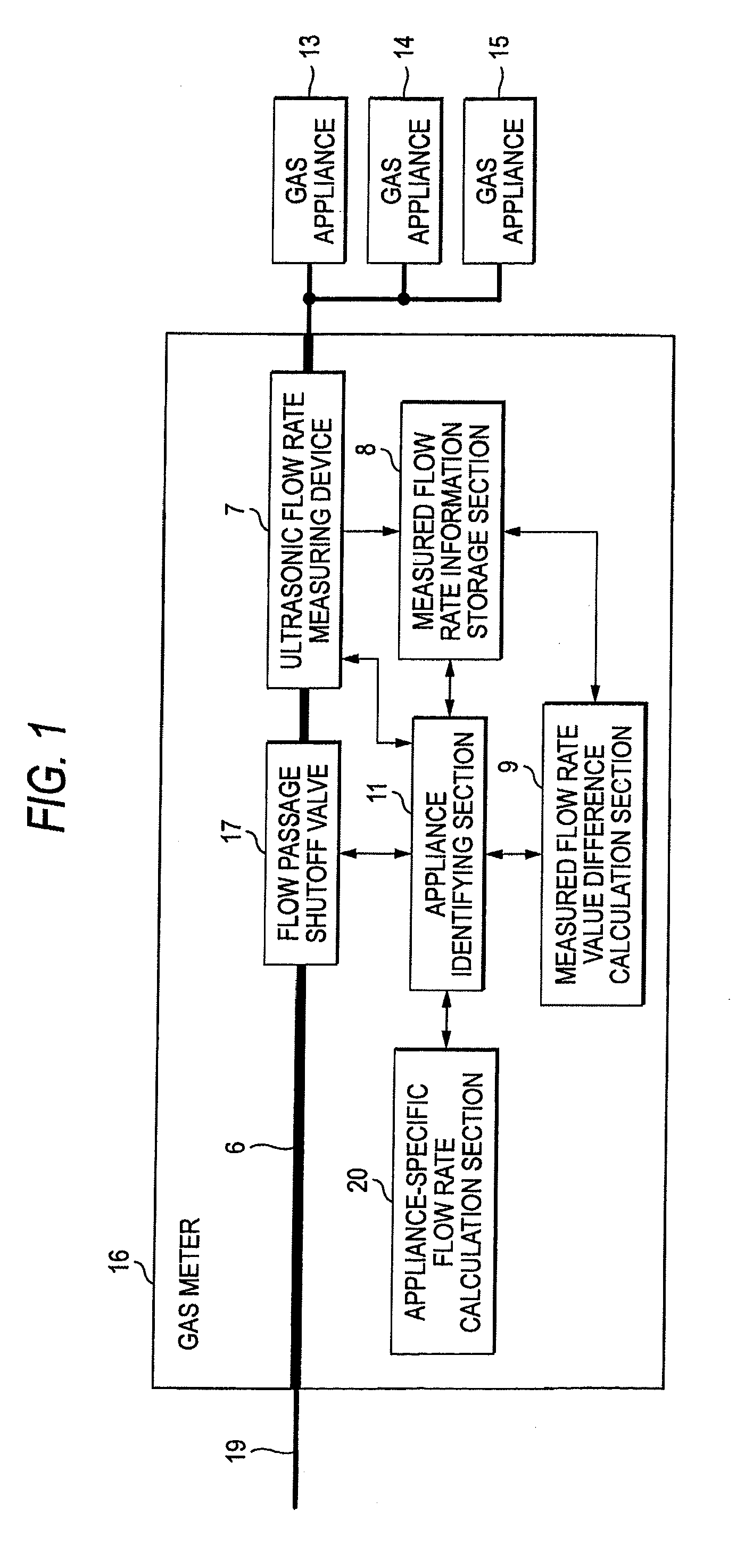
[0041]FIG. 1 show a block diagram of a gas meter 16 working as a flow rate measuring apparatus of the embodiment of the present invention.

[0042]In FIG. 1, the gas meter 16 has a flow passage 6, an ultrasonic flow rate measuring device 7, a measured flow rate information storage section 8, a measured flow rate value difference calculation section 9, and an appliance identifying section 11. The gas meter 16 is disposed in the flow passage 6 and includes a flow passage shutoff valve 17 for shutting off gas in the event of emergency and an appliance-specific flow rate calculation section 20.

[0043]The ultrasonic flow rate measuring device 7 measures a flow rate of gas serving as a fluid that flows in the flow passage 6 by emitting an ultrasonic wave to the gas, and a common ultrasonic flow measurement device can be used. The measured flow rate information storage section 8 stores objec...


PUM


Abstract

There is provided a technique for accurately identifying an appliance which uses the fluid from a viewpoint of the range of a change in flow rate value. An ultrasonic flow rate measuring device 7 measures a flow rate value of gas flowing in a flow passage 6 of a gas meter 16, and a measured flow rate information storage section 8 stores a measured flow rate value. A measured flow rate value difference calculation section 9 calculates a measured flow rate value difference within a predetermined period corresponding to an amount of change occurred in a measured flow rate value. An appliance identifying section 11 identifies an appliance which uses the fluid or leakage by determining whether or not the measured flow rate value difference is a predetermined threshold or less.

Description

TECHNICAL FIELD[0001]The present invention relates to a technique for identifying an appliance which uses the fluid or leakage by utilization of a change in a flow rate of fluid.BACKGROUND ART[0002]As shown in FIG. 8, a flow rate measuring apparatus of this type has a gas flow rate measurement unit 1 that measures a flow rate of gas flowing in a gas flow passage; a flow rate increase detection unit 2 that detects an increase in flow rate on the basis of a measurement result; a flow rate increment / decrement detection unit 3 that detects an instantaneous incremental / decremental change in gas flow rate according to an increase in flow rate; an appliance identifying unit 4 that determines initiation of use of a new gas combustion appliance when the instantaneous incremental / decremental change is detected; and a flow rate registration unit 5 that registers the increase in gas flow rate detected by the flow rate increase detection unit as an increase in the flow rate of gas arising from i...

Claims


Application Information

Patent Timeline
IPC IPC(8): G01F3/22
CPCF23N1/002F23N5/184F23N5/242G01F15/068F23N2031/18G01F1/667F23N2005/185F23K2900/05001G01F1/66F23N2231/18G01F25/15
Inventor BESSYO, DAISUKEMIYATA, HAJIMEITOU, YOUICHI
Owner PANASONIC CORP
Why Eureka
Try Eureka