Grommet

a technology of grommets and groms, which is applied in the field of grommets, can solve the problems of abrasive, sharp remaining edge of the cut or punched portion of the aperture, and the known grommets, especially for aerospace use, are quite complex, and achieve the effect of easy removal and replacement of the component aperture and more stiffness

Active Publication Date: 2010-06-10
SHORT BROTHERS
View PDF19 Cites 10 Cited by
  • Summary
  • Abstract
  • Description
  • Claims
  • Application Information

AI Technical Summary

Benefits of technology

[0016]In a preferred embodiment of the grommet of the present invention there may be provided a radial slit through the whole grommet at one wall position thus, the grommet is still in a single piece but may be opened out or made smaller in circumferential size. The purpose of the radial slit is to provide a means whereby the grommet may easily be removed from the component aperture and replaced, without having to remove or displace the articles passing through the aperture.
[0017]In a further preferred embodiment, the grommet may be provided with means to restrain an article passing through the grommet when installed in the aperture. Such means may comprise at least one generally axially directed restraining member and may preferably be formed at one axial end of the grommet. The at least one restraining member may be formed as part of one or more of the axially directed resilient fingers, but preferably, the at least one restraining member may be provided at the end of the grommet having the lip portion and be associated with the wall portion and / or the lip portion as it is believed that this arrangement provides more stiffness to the restraining member.

Problems solved by technology

Whether or not there is a flange portion, the remaining edge of the cut or punched portion of the aperture is often sharp and abrasive to items such as those described above which are required to pass through the aperture.
Known grommets, especially for aerospace use have been quite complex with regard to time and effort required to fit them and are consequently costly.

Method used


Image

  • Grommet
  • Grommet
  • Grommet

Examples


Embodiment Construction

[0027]Referring now to the drawings and where the same features are denoted by common reference numerals.

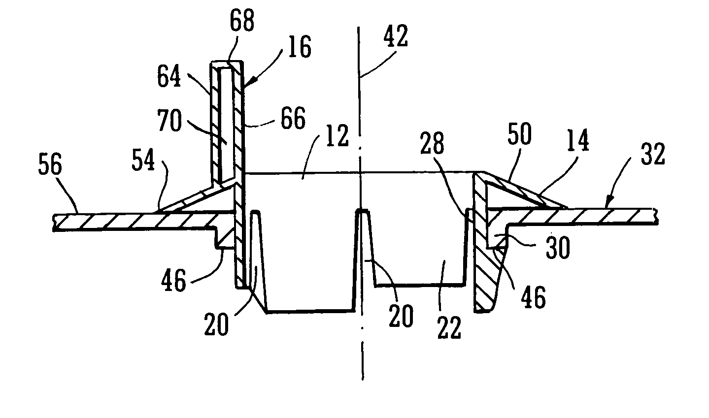
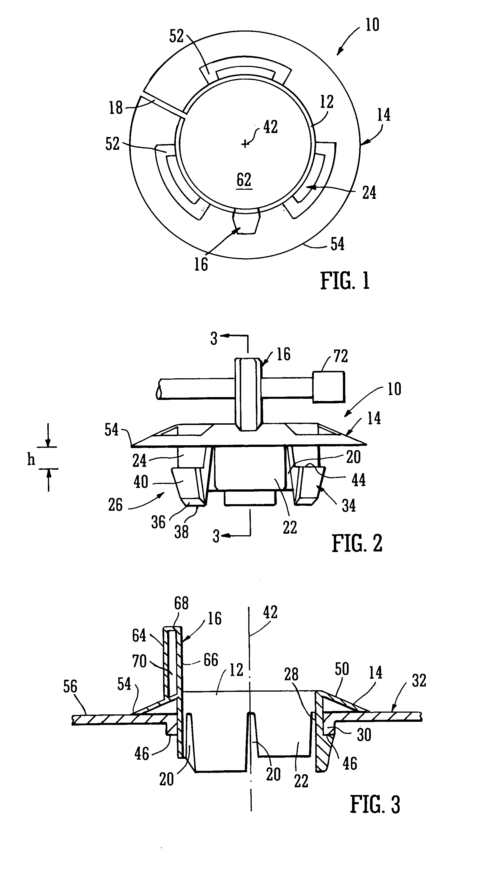
[0028]A grommet according to the present invention is indicated generally at 10 and comprises a generally cylindrical wall portion 12; a lip member 14 formed at one end of the grommet; and, a restraining member 16. The wall portion 12 and lip 14 has a radially directed slit 18 passing through the grommet in the axial direction thus making the grommet circumferentially discontinuous. The wall portion 12 is divided up in its lower region by axially directed slots 20 which effectively render the lower region of the wall portion into a plurality of resilient finger portions comprising skirt panels 22 and resilient fingers 24 which are also provided with retention means 26 (described below) to permit easy insertion of the grommet 10 into a hole 28 having a flange 30 in a sheet structural member indicated in part at 32 (whilst this embodiment is described with reference to a grommet 10...


PUM


Abstract

A grommet (10) for use with the face or web of a component such as sheet material for protecting the surface of articles passing through apertures formed in said component, said grommet comprising a generally cylindrical main wall portion (12) having adjacent one axial end thereof an outwardly extending lip portion(14), said main wall portion including a plurality of axially directed resilient fingers (24), at least some of said fingers having means (26) for resisting disengagement of said grommet from said component.

Description

[0001]The present invention relates to a grommet for use in locating and protecting the surface of articles such as electrical cables and pipes passing through apertures in the face or web of a component.[0002]Large structures such as aeroplanes, for example, utilise large quantities of relatively thin materials especially in internal structure such a fuselage frames, wing ribs and the like. It is frequently necessary to make or utilize existing apertures in such components to enable electrical cables and tubes, for example, to pass therethrough. The aperture itself is either cut, machined or punched and is often provided with a flange portion around the periphery of the aperture. Whether or not there is a flange portion, the remaining edge of the cut or punched portion of the aperture is often sharp and abrasive to items such as those described above which are required to pass through the aperture.[0003]In addition to the need for cables and the like to merely pass through the aper...

Claims


Application Information

Patent Timeline
Patent Type & Authority Applications(United States)
IPC IPC(8): F16L5/00
CPCY10T16/05F16L5/027
Inventor MAGENNIS, PAULQUINN, KEVIN
Owner SHORT BROTHERS
Why Eureka
Try Eureka