
Method and apparatus for forming contact layers for continuous workpieces

a technology of contact layer and workpiece, which is applied in the direction of vacuum evaporation coating, sustainable manufacturing/processing, and final product manufacturing, etc., can solve the problems of affecting the overall quality of the deposited film, introducing unwanted contamination and particle formation in the reaction chamber, and affecting the efficiency of the device. , to achieve the effect of reducing the effective series resistance of the devi

Inactive Publication Date: 2010-06-10
SOLOPOWER
View PDF20 Cites 29 Cited by
  • Summary
  • Abstract
  • Description
  • Claims
  • Application Information

AI Technical Summary

Benefits of technology

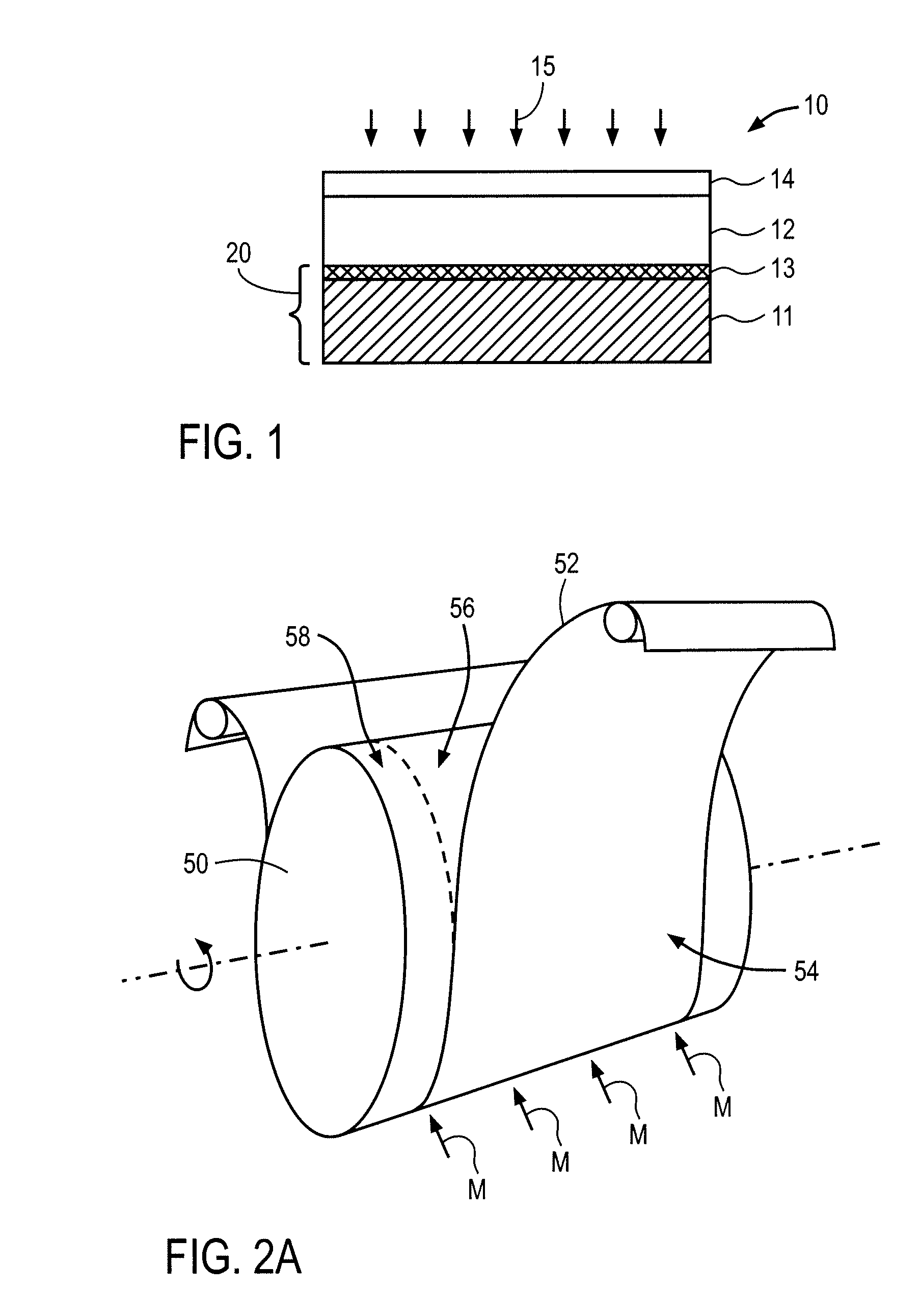
[0007]The structure of a conventional Group IBIIIAVIA compound photovoltaic cell such as a Cu(In,Ga,Al)(S,Se,Te)2 thin film solar cell is shown in FIG. 1. The device 10 is fabricated on a substrate 11, such as a sheet of glass, a sheet of metal, an insulating foil or web, or a conductive foil or web. The absorber film 12, which includes a material in the family of Cu(In,Ga,Al)(S,Se,Te)2, is grown over a contact layer 13 or conductive layer, which is previously deposited on the substrate 11 and which acts as the electrical contact to the device. The absorber film 12 is typically formed by a co-deposition approach or a two-stage approach. In co-deposition approach all components of the absorber film 12 (i.e. Cu, In, Ga and Se) are delivered onto the contact layer of a base heated to a temperature in the range of 400-600° C. These components react under the influence of heat and form the compound. In a two-stage process a precursor layer including Group IB and Group IIIA elements are first deposited on the contact layer during the first stage of the process. In the second stage the precursor film is heated up to temperatures in the range of 400-600° C. and reacted with one of Se and S to form the CIGS(S) type absorber layer. The substrate 11 and the contact layer 13 form a base 20 on which the absorber film 12 is formed. Various conductive layers comprising Mo, Ta, W, Ti, and their alloys and nitrides have been used in the solar cell structure of FIG. 1. If the substrate itself is a properly selected conductive material, it is possible not to use a contact layer 13, since the substrate 11 may then be used as the ohmic contact to the device. After the absorber film 12 is grown, a transparent layer 14 such as a cadmium sulfide (CdS) layer, a transparent conductive oxide (TCO) film such as a zinc oxide (ZnO) layer or a CdS / ZnO stack is formed on the absorber film. Radiation 15 enters the device through the transparent layer 14. Metallic grids (not shown) may also be deposited over the transparent layer 14 to reduce the effective series resistance of the device.

Problems solved by technology

However, the cost of electricity generated using silicon-based solar cells is higher than the cost of electricity generated by the more traditional methods.
In addition, such deposits can cause the flexible substrate to deform non-uniformly, affecting the overall quality of the deposited film.
Such corrosion introduces unwanted contamination and particle formation in reaction chambers where the second stage of the process is carried out.

Method used


Image

  • Method and apparatus for forming contact layers for continuous workpieces
  • Method and apparatus for forming contact layers for continuous workpieces
  • Method and apparatus for forming contact layers for continuous workpieces

Examples


Embodiment Construction

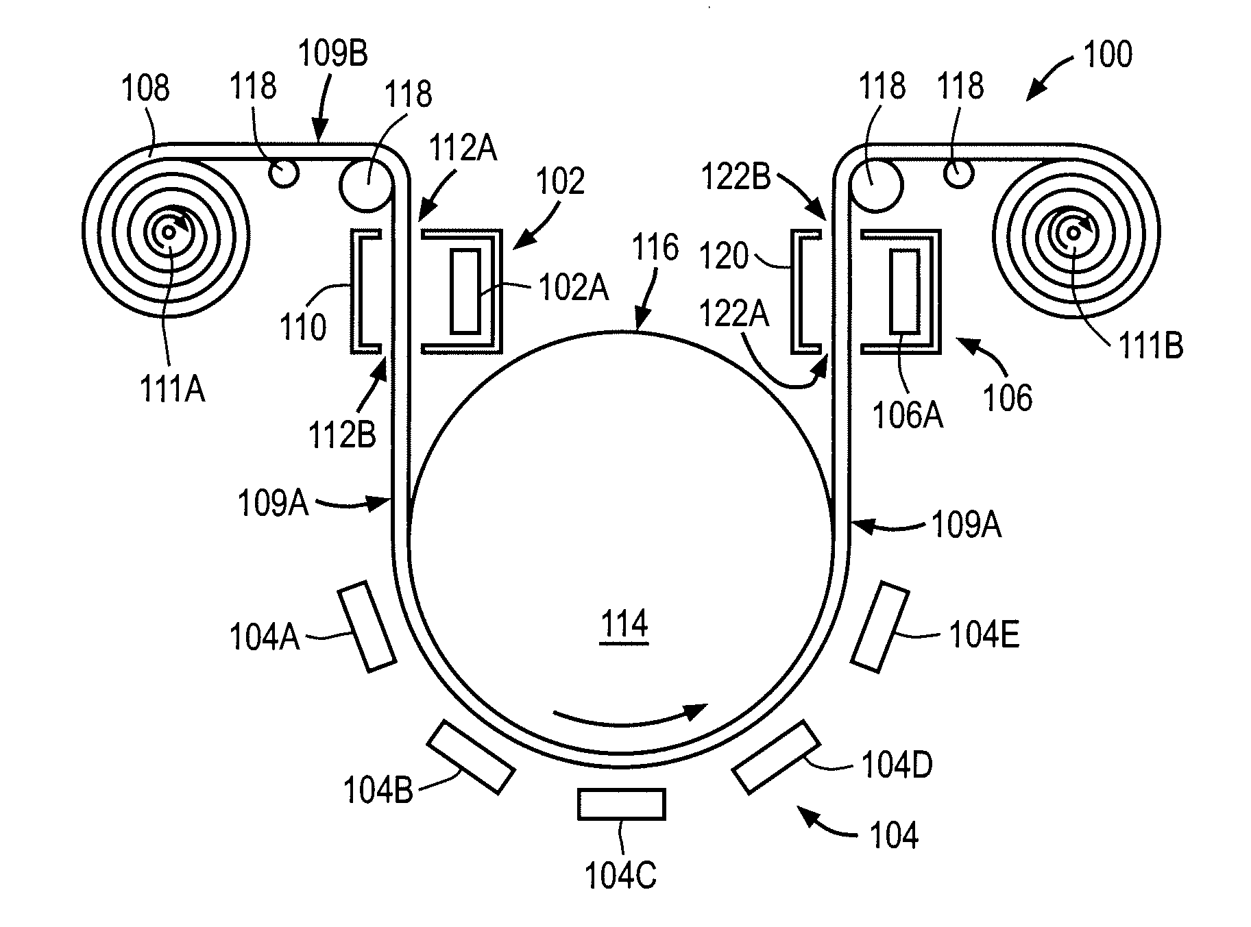
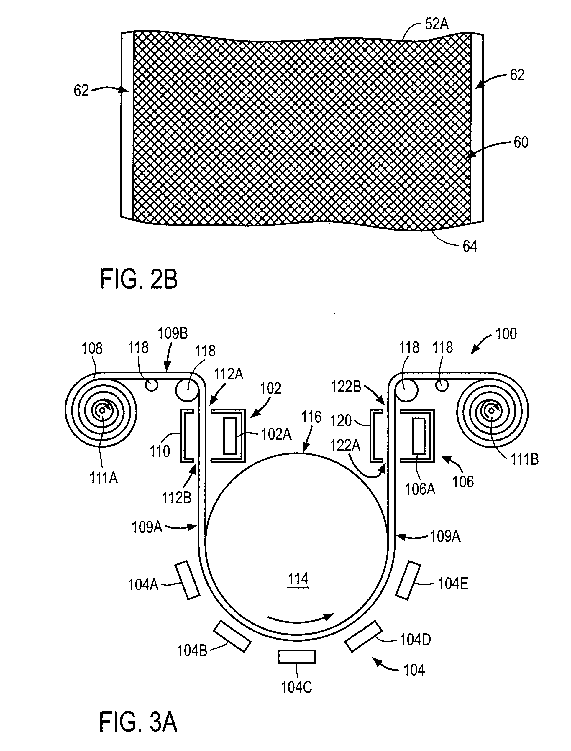
[0030]The embodiments described herein provide a roll-to-roll sputter deposition system for depositing thin films on flexible continuous substrates for manufacturing CIGS type solar cells on such substrates. The system may be used to form bases or protected base structures including a flexible substrate and one or more conductive layers formed on the substrate. The conductive layers may be formed over at least one of a back surface and a front surface of the flexible substrate.

[0031]In one embodiment, initially a back conductive layer is formed over a back surface of a continuous substrate by depositing a first conductive material in a first deposition station while the flexible substrate is advanced towards a second deposition station including a support base or drum of the system. The back conductive layer entirely covers the back surface without excluding any back surface portion. Next, a front partial conductive layer is formed by depositing a second conductive material over a f...


PUM

PropertyMeasurementUnit
temperatureaaaaaaaaaa
temperaturesaaaaaaaaaa
thicknessaaaaaaaaaa

Abstract

The present invention provides a roll to roll system and a method to sputter deposit various conductive films on a back surface and a front surface of a continuous substrate to form protected base structures for Group IBIIIAVIA thin film solar cells. In one embodiment of the invention, a back protection film is sputter deposited onto the entire back side of the substrate in a first deposition station without transferring heat from the substrate. Next, a first front film is sputter deposited in a second deposition station to partially cover the front side of the substrate while heat is transferred from substrate by a cooling surface of a cooling mechanism in the second deposition station. The second film does not cover the edges of the substrate to avoid contaminating the cooling surface with the depositing material. Other embodiments are directed to specifics regarding the depositing of these films, adding other films, and a system for depositing the films.

Description

CLAIM OF PRIORITY[0001]This application claims priority to U.S. Provisional Application Ser. No. 61 / 200,961 filed Dec. 5, 2008, the contents of which are incorporated herein by reference.BACKGROUND[0002]1. Field of the Invention[0003]The inventions relate to deposition methods and, more particularly, to methods for physical vapor deposition of thin films on a flexible surface in a roll-to-roll fashion for manufacturing solar cells.[0004]2. Description of the Related Art[0005]Solar cells are photovoltaic devices that convert sunlight directly into electrical power. The most common solar cell material is silicon, which is in the form of single or polycrystalline wafers. However, the cost of electricity generated using silicon-based solar cells is higher than the cost of electricity generated by the more traditional methods. Therefore, since early 1970's there has been an effort to reduce cost of solar cells for terrestrial use. One way of reducing the cost of solar cells is to develop...

Claims


Application Information

Patent Timeline
Patent Type & Authority Applications(United States)
IPC IPC(8): C23C14/34C23C14/56
CPCC23C14/042C23C14/165C23C14/541C23C14/562Y02E10/541H01L31/03928H01L31/0749H01L31/18H01L31/0322Y02P70/50
Inventor PINARBASI, MUSTAFAFREITAG, JAMESVASQUEZ, JORGEBASOL, BULENT M.
Owner SOLOPOWER
Learn More