Method for maximum data collection with a control moment gyroscope controlled satellite

a technology of gyroscope control and maximum data collection, which is applied in the direction of vehicle position/course/altitude control, process and machine control, instruments, etc., can solve the problem that the method does not provide the minimum time maneuver for moving the satellite, and achieve the effect of shortening the duration

Inactive Publication Date: 2010-06-10
BAILEY DAVID A
View PDF2 Cites 26 Cited by
  • Summary
  • Abstract
  • Description
  • Claims
  • Application Information

AI Technical Summary

Problems solved by technology

However, this prior art method does not provide the minimum time maneuver for moving the satellite to the desired imaging attitude and attitude rate.

Method used


Image

  • Method for maximum data collection with a control moment gyroscope controlled satellite
  • Method for maximum data collection with a control moment gyroscope controlled satellite
  • Method for maximum data collection with a control moment gyroscope controlled satellite

Examples


Embodiment Construction

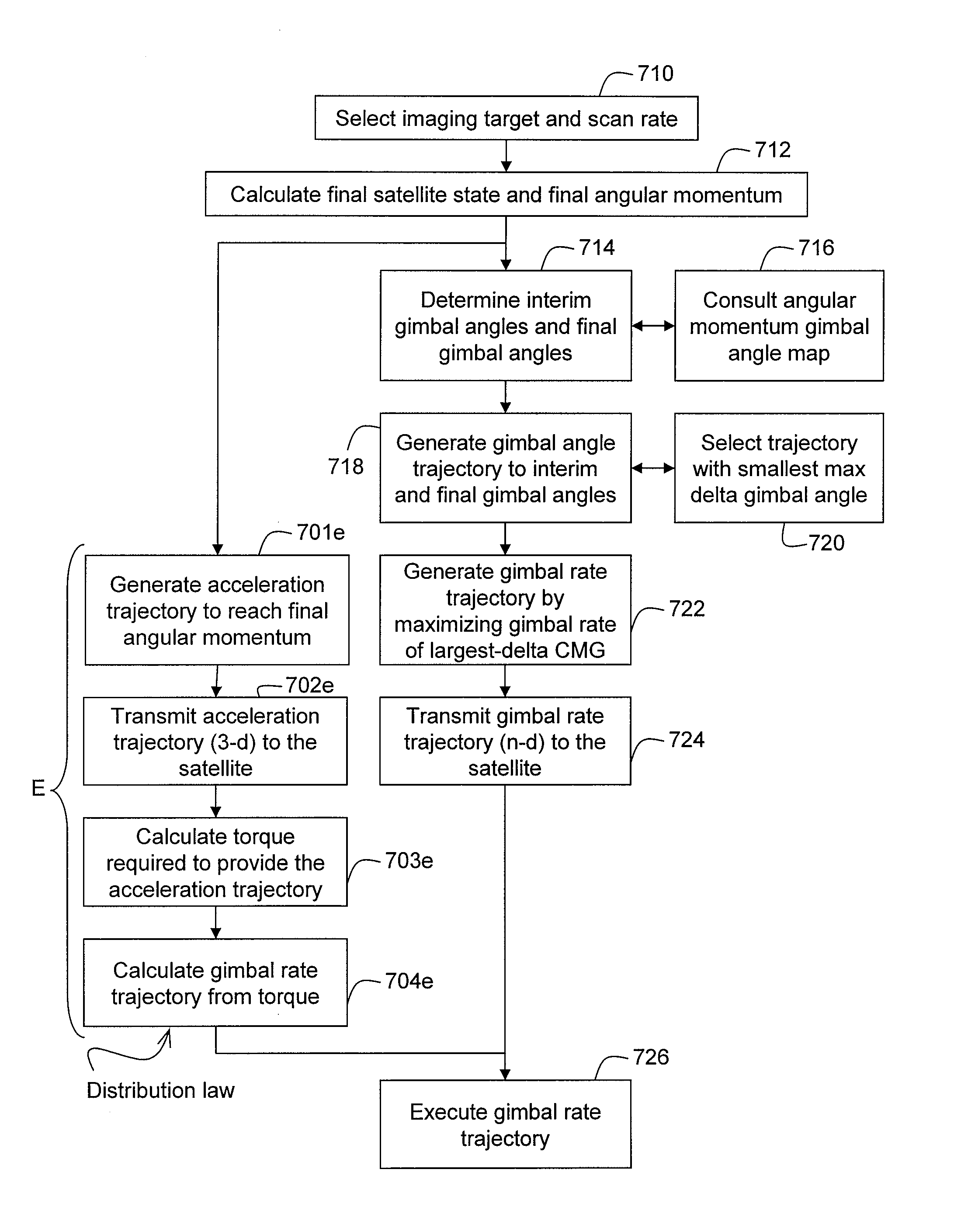
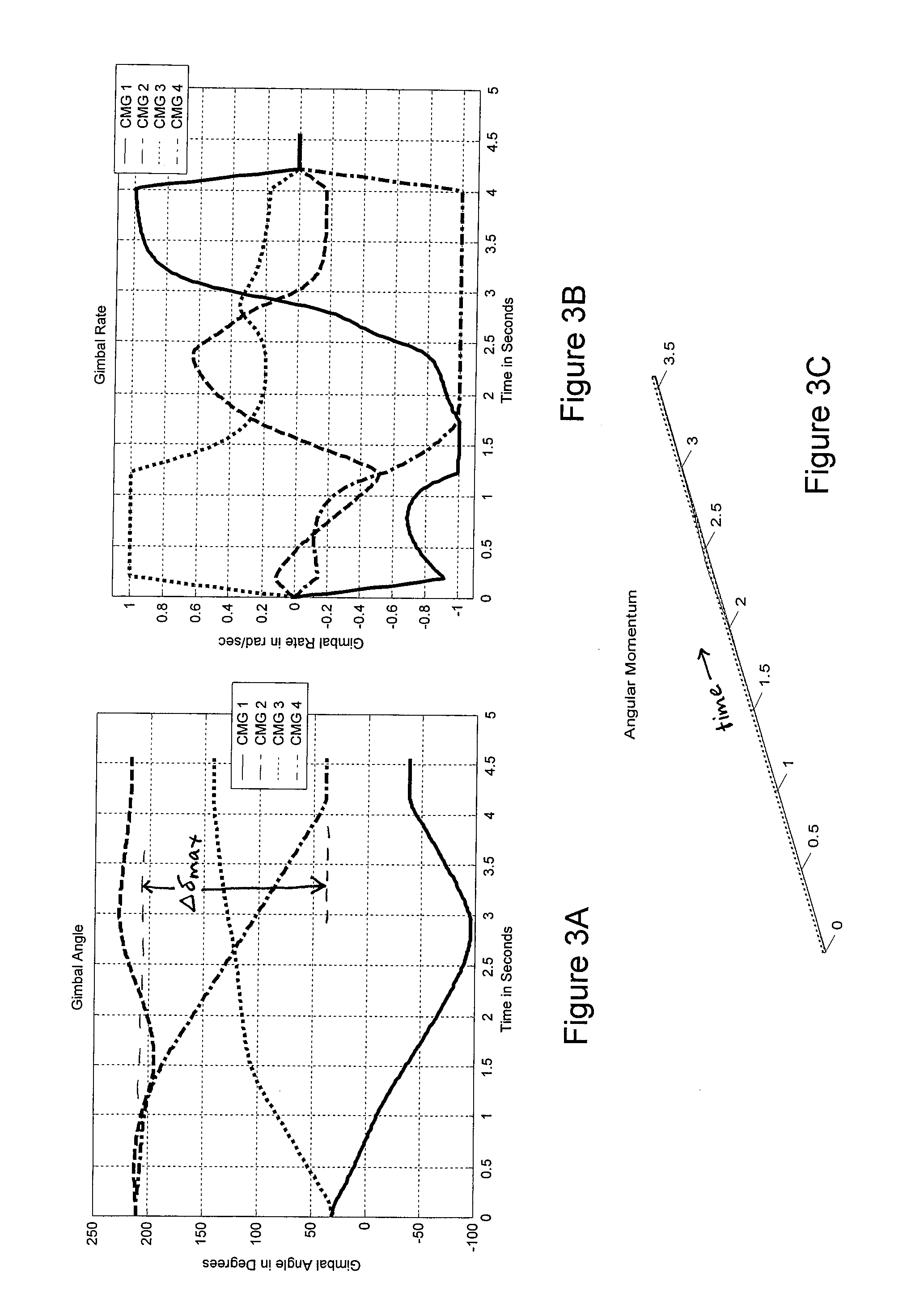
[0051]The present invention relates, for example, to a method for maneuvering an imaging satellite, and more particularly a method for commanding control moment gyroscopes on an imaging satellite to change the attitude of the satellite. In one embodiment, the method includes generating a gimbal rate trajectory for the CMG's, transmitting the gimbal rate trajectory to the satellite, and moving each CMG along the gimbal rate trajectory to execute the maneuver. The maneuver is designed in gimbal angle space, by determining the shortest path for the CMG's to move from the initial set of gimbal angles to the final, desired gimbal angles. In the prior art, the maneuver is designed in angular momentum space, rather than gimbal angle space, and the satellite is commanded in terms of a satellite acceleration trajectory (in 3 dimensions) rather than a gimbal rate trajectory (in n dimensions). In embodiments of the present invention, the maneuver designed in gimbal angle space has a shorter du...


PUM


Abstract

The present invention relates to a method for maneuvering an imaging satellite, and more particularly a method for commanding control moment gyroscopes on an imaging satellite to change the attitude of the satellite. In one embodiment, a method for generating a gimbal rate trajectory for maneuvering a satellite to point to a target includes providing a final attitude for pointing to the target and a final satellite rate for imaging the target, providing an initial attitude and an initial set of gimbal angles, and determining a gimbal rate trajectory from the initial set of gimbal angles to a final set of gimbal angles.

Description

CROSS-REFERENCE TO RELATED APPLICATION(S)[0001]This application claims priority to and the benefit of U.S. Provisional Patent Application No. 61 / 199,578 filed on Nov. 17, 2008, the entire contents of which are incorporated herein by reference.FIELD OF THE INVENTION[0002]The present invention relates to a method for maneuvering an imaging satellite, and more particularly a method for commanding control moment gyroscopes on an imaging satellite to change the attitude of the satellite.BACKGROUND OF THE INVENTION[0003]Image satellite planning is a planning process used to determine the pointing path that an imaging satellite takes as it passes over a set of targets on the ground. In order to take an image of a particular target on the ground, the satellite needs to be pointed in the correct direction, meaning the satellite has a particular attitude. Additionally, in order to take a scanning image over a target, the satellite needs to move at the correct scanning velocity, meaning the sa...

Claims


Application Information

Patent Timeline
Patent Type & Authority Applications(United States)
IPC IPC(8): B64G1/28G05D1/08
CPCB64G1/1021G05D1/0883B64G1/286B64G1/244
Inventor BAILEY, DAVID A.
Owner BAILEY DAVID A
Why Eureka
Try Eureka