Vehicle seat

a seat and vehicle technology, applied in the field of vehicle seats, can solve the problems of large load on the legs and other parts of the occupants, and achieve the effect of reducing the strength

Active Publication Date: 2010-06-10
NISSAN MOTOR CO LTD
View PDF10 Cites 85 Cited by
  • Summary
  • Abstract
  • Description
  • Claims
  • Application Information

AI Technical Summary

Benefits of technology

[0008]In another aspect, the present disclosure relates to a vehicle seat comprising a seat cushion frame further comprising a pair of side frames and a front cross member located on a front side of the vehicle seat. The front cross member extends between the side frames and at least one means for supporting connected to the front cross member and arranged vehicle forward of the front cross member, the at least one means for supporting having a lower strength than the front cross member and being configured to support legs of an occupant in the event of a rear-end vehicular crash.

Problems solved by technology

Accordingly, when such rear-end collisions occur, a front side portion of the front cross member may impact the calves (or other portions of the legs) of the occupant, which may result in a large load to the legs and other parts of the occupant.

Method used


Image

  • Vehicle seat
  • Vehicle seat
  • Vehicle seat

Examples


embodiment 1

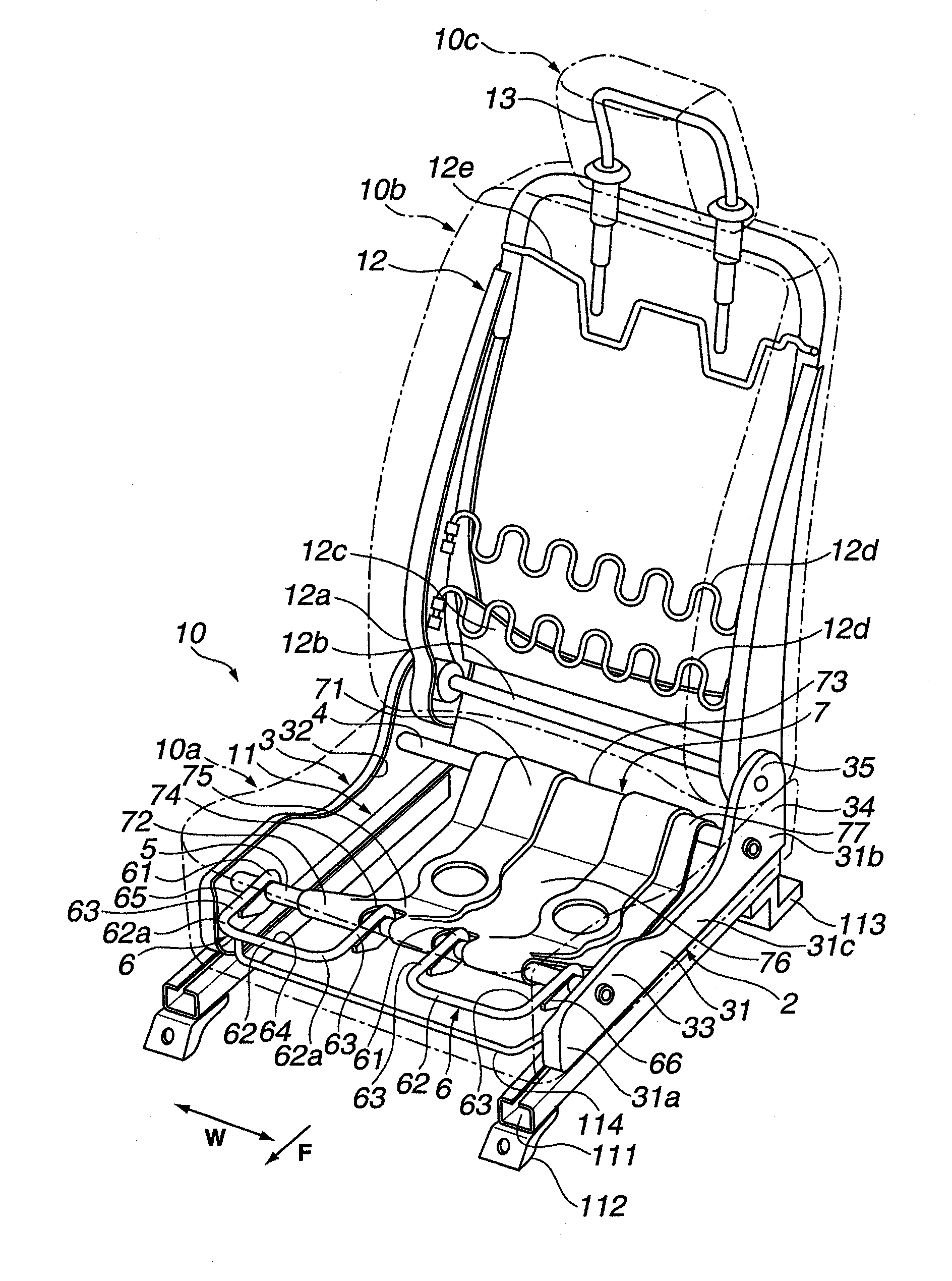
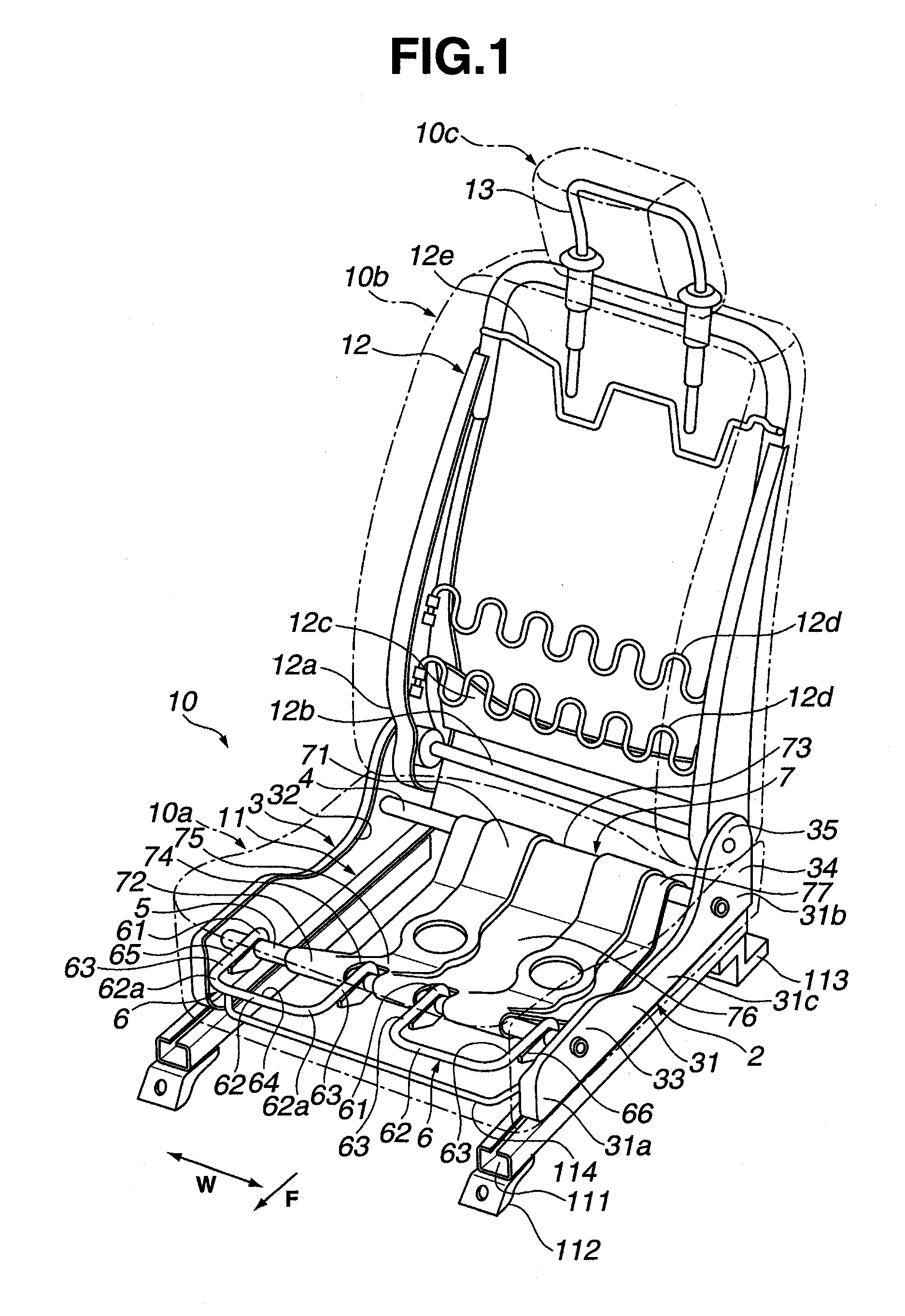
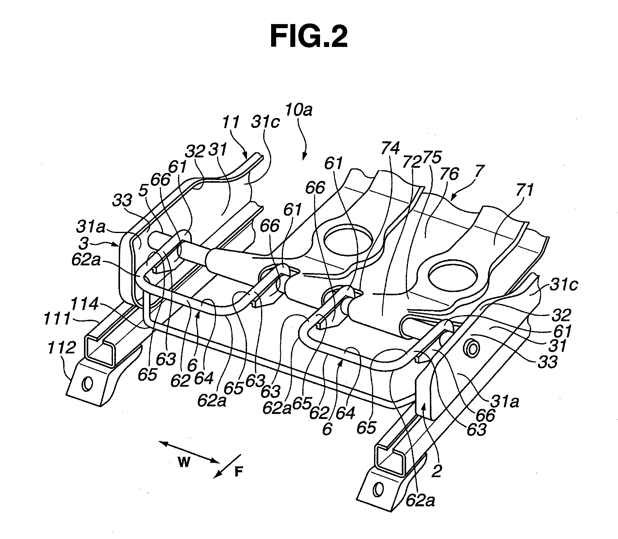
[0019]The following describes a construction according to a first exemplary embodiment. In FIG. 1, an arrow F indicates a forward direction of vehicle seat 10 (or seat cushion 10a), whereas an arrow W indicates a lateral direction or cross direction of vehicle seat 10 (or seat cushion 10a).

[0020]As shown in FIG. 1, vehicle seat 10 according to the first exemplary embodiment may include seat cushion 10a on which an occupant may sit, and which is indicated by phantom lines. A seat back 10b may be provided to extend vertically upward from a rear portion of seat cushion 10a. A headrest 10c may be provided to extend vertically upward from an upper portion of seat back 10b. Seat cushion 10a, seat back 10b, and headrest 10c may have a seat cushion frame 11, a seat back frame 12, and a headrest frame 13, respectively, which may be framework members made of metal.

[0021]Seat cushion frame 11 may be composed of a left side frame 2 and a right side frame 3, which may be arranged at left and rig...

embodiment 2

[0053]The following describes a construction according to a second exemplary embodiment. As shown in FIG. 5, a leg support member 120 may be provided forward (in the direction of arrow F) of and projecting from front cross member 5. Leg support member 120 may extend substantially across the entire width of seat cushion 10a in the lateral direction W. Namely, a single leg support member 120 may be provided for both legs of an occupant seated in the seat 10.

[0054]Leg support member 120 may be formed substantially in a U-shape in a plan view, with a lateral portion 122, which may extend in the lateral direction W of seat cushion 10a, and connecting portions 123, which may extend toward front cross member from side portions 122a of lateral portion 122 at which leg support member 120 may be plastically bent. Leg support member 120 may be formed by bending a hollow cylindrical rod (pipe) made of metal, or other material, which may have a lower strength than front cross member 5. Base end ...

embodiment 3

[0060]The following describes a construction according to a third exemplary embodiment. As shown in FIG. 6, a leg support member 130 may be provided forward (in the direction of arrow F) of and projecting from front cross member 5 and extending in the lateral direction W of seat cushion 10a. Leg support member 130 may be composed of leg support portions 130a provided for the legs of an occupant seated in the seat, and a left-right-coupling portion 130b that may couple the leg support portions 130a.

[0061]Each leg support portion 130a, which may constitute leg support member 130, may be formed substantially in a U-shape in a plan view, with a lateral portion 132 extending in the lateral direction W of seat cushion 10a and connecting portions 133 extending toward front cross member 5 from side portions 132a at which leg support member 130 may be plastically bent. Leg support portions 130a and left-right-coupling portion 130b may be integrally formed by bending a hollow cylindrical rod...


PUM


Abstract

A vehicle seat includes a seat cushion frame which comprises a pair of side frames and a front cross member located on a front side of the vehicle seat, the front cross member extending between the side frames and at least one leg support member is connected to the front cross member, and is arranged vehicle forward of the front cross member, wherein the at least one leg support member comprises at least a portion having a strength lower than a strength of the front cross member.

Description

CROSS-REFERENCE TO RELATED APPLICATIONS[0001]The present application claims priority from Japanese Patent Application No. 2008-309191, filed Dec. 4, 2008. The contents of the priority application are hereby incorporated by reference in their entirety.BACKGROUND OF THE DISCLOSURE[0002]1. Field of the Disclosure[0003]The present invention relates to a vehicle seat capable of reducing a load that is applied to an occupant seated in the vehicle seat during a vehicle collision.[0004]2. Description of the Related Art[0005]Japanese Patent Application Publication 2006-193040 discloses a seat cushion frame which is provided with side frames arranged in parallel on left and right sides, a front cross member extending between front end portions of the side frames, and a rear cross member extending between rear end portions of the side frames. The front cross member is formed by bending a substantially-rectangular flat metal material. During a head-on collision, a load resulting from a forward ...

Claims


Application Information

Patent Timeline
Patent Type & Authority Applications(United States)
IPC IPC(8): B60N2/42B60R21/00B60N2/90
CPCB60N2/4228B60N2/4263B60N2/42709B60N2/68B60N2/995
Inventor SAWADA, TAMOTSU
Owner NISSAN MOTOR CO LTD
Why Eureka
Try Eureka