Centrifugal wheel

a centrifugal wheel and centrifugal technology, applied in the field of centrifugal wheels, can solve the problems of inability to meet the needs of large-sized vehicles, inconvenient installation, and the dependence of traditional pneumatic tires on air, and achieve the effects of convenient manufacture, installation on a vehicle, and us

Inactive Publication Date: 2010-06-10
MCCUE FAMILY TRUST
View PDF10 Cites 29 Cited by
  • Summary
  • Abstract
  • Description
  • Claims
  • Application Information

AI Technical Summary

Benefits of technology

[0017]The present general inventive concept further provides a centrifu

Problems solved by technology

Factors contributing to inefficiencies in current automotive technology include weight and friction.
While this type of tire works well with small, lightweight cars, it does not lend itself to larger, heavier vehicles especially when these vehicles attempt to accelerate and stop.
These deficiencies are due to the fact that, while friction is a disadvantage when related to efficiency, friction is an advantage when related to accelerating and stopping.
Another deficiency of a traditional pneumatic tire relates to its dependence on air.
A tire which has lost sufficient pressure to cause it to become distorted at the bottom will impair the stability of the vehicle and may further damage the tire if it is driven in this condition.
Continuing to drive the vehicle with an absolutely flat tire will likely damage the tire beyond repair, possibly damage the w

Method used


Image

  • Centrifugal wheel
  • Centrifugal wheel
  • Centrifugal wheel

Examples


Embodiment Construction

[0048]Reference will now be made in detail to the embodiments of the present general inventive concept, examples of which are illustrated in the accompanying drawings, wherein like reference numerals refer to like elements throughout. The embodiments are described below in order to explain the present general inventive concept by referring to the figures.

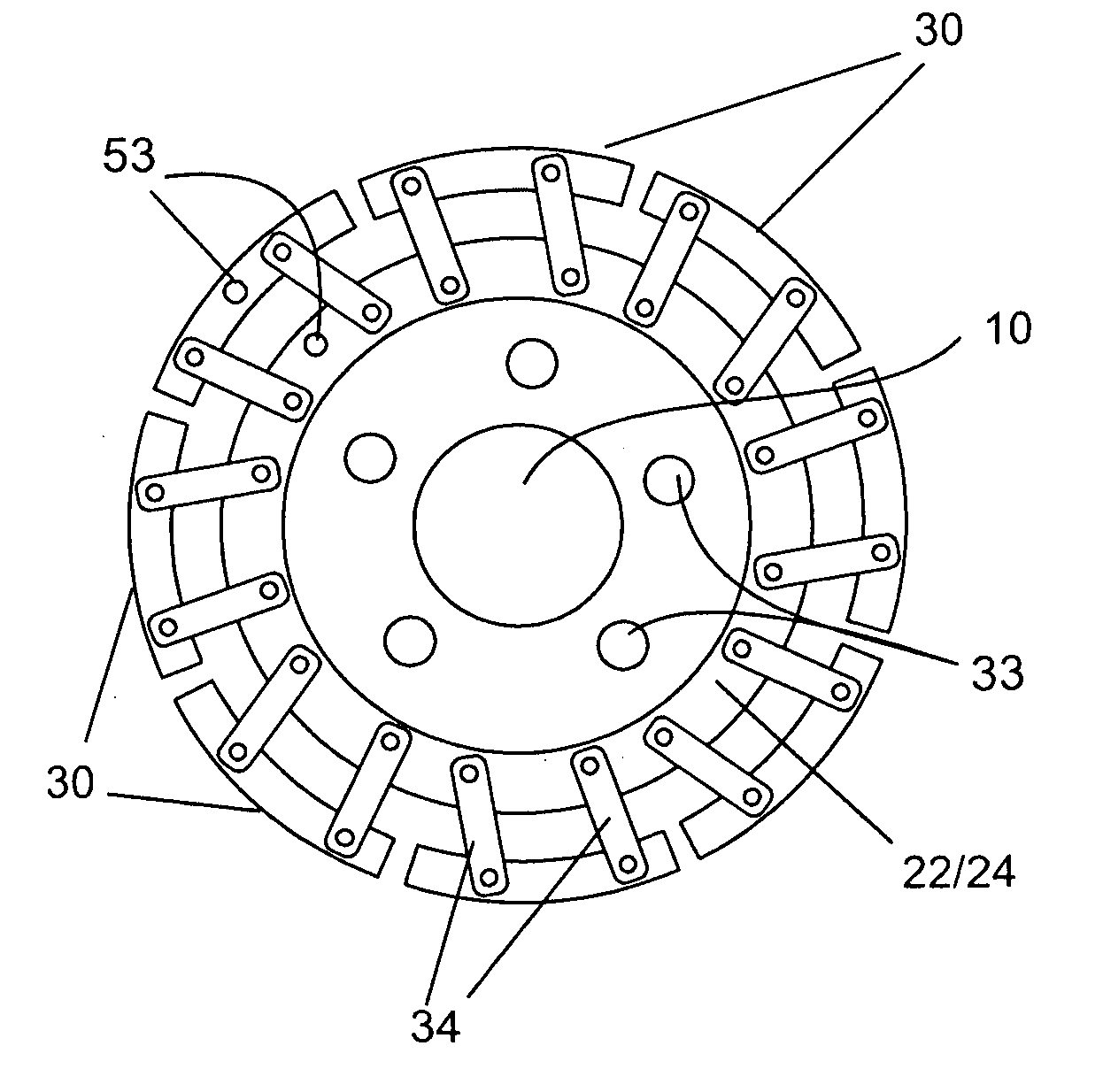
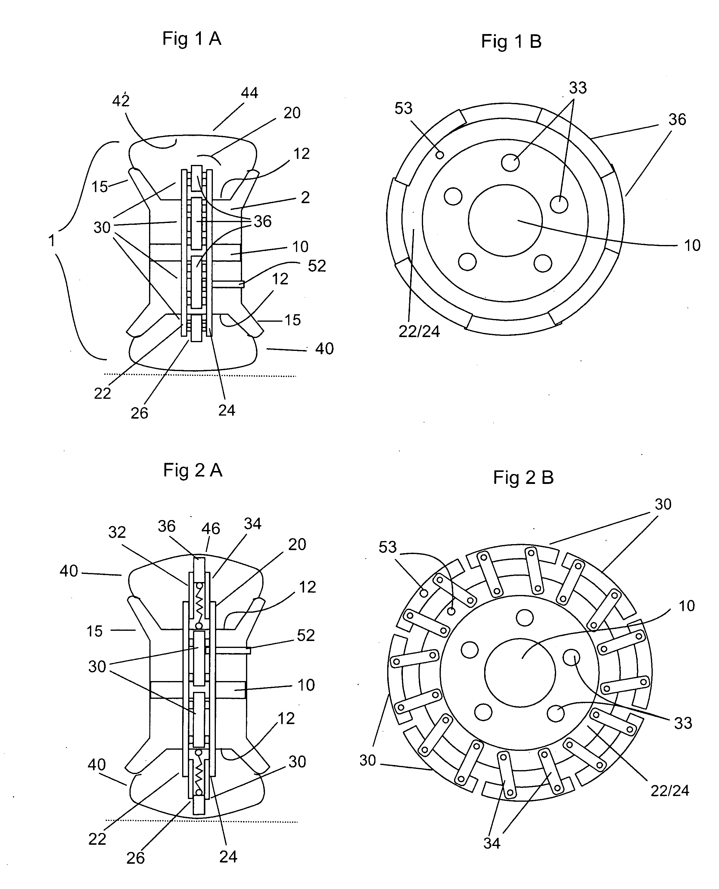
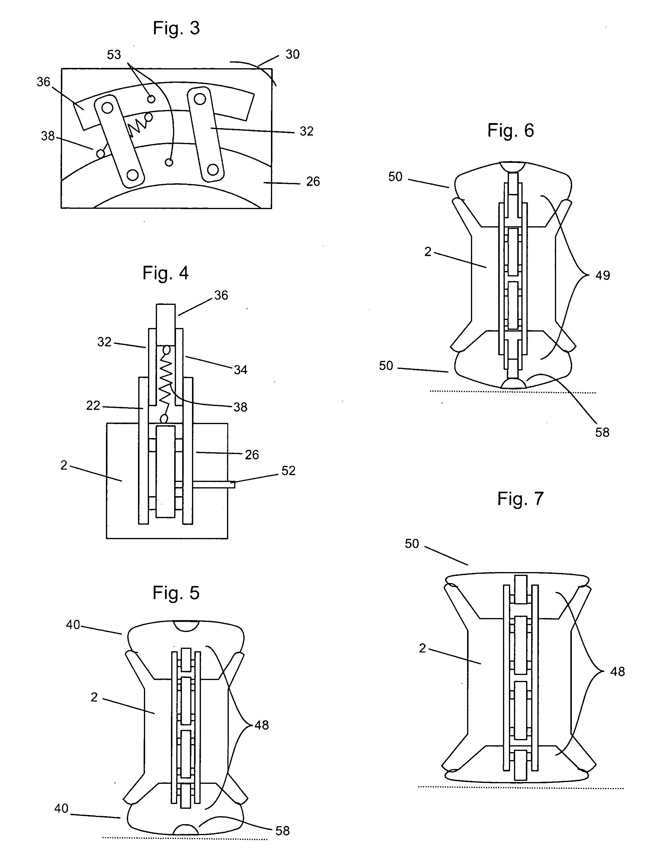
[0049]As illustrated in FIG. 1A, a centrifugal wheel assembly 1 includes a wheel 2 having an axel portion 10 with an outer surface 12 and rim portions 15 extending therefrom. The wheel 2 includes lug holes 33 to accommodate lugs therein for securing the wheel 2 to a vehicle.

[0050]Abutting the outer surface 12 is a wheel engagement base assembly 20. In an exemplary embodiment, the wheel engagement base assembly 20 is a single unit that completely surrounds the outer surface 12. Nevertheless, it will be appreciated that the engagement base assembly 20 may be a plurality of units that connect about the outer surface 12, e.g., eight uni...


PUM


Abstract

A centrifugal wheel apparatus for a vehicle having a plurality of pivoting elements attachable to an interior of a vehicle wheel that, when subjected to centripetal force, pivot away from the vehicle wheel and toward a pneumatic tire attached to the vehicle wheel to reshape the pneumatic tire into a dome thereby decreasing surface contact between the vehicle and a surface so that the vehicle may travel with less resistance and increased economy.

Description

CROSS-REFERENCE TO RELATED APPLICATION[0001]This application for patent claims the benefit of priority from U.S. Provisional Patent Application Ser. No. 61 / 144,208 filed Jan. 13, 2009, the disclosure of which is incorporated herein by reference in its entirety.BACKGROUND OF THE INVENTION[0002]1. Field of the Invention[0003]The present general inventive concept relates to a centrifugal wheel for a vehicle, and in particular, to a vehicle wheel having a plurality of pivoting elements that, when subjected to centripetal force, pivot to reshape a pneumatic tire attached to the wheel.[0004]2. Description of the Related Art[0005]The automotive industry is on a quest to increase fuel economy. Factors contributing to inefficiencies in current automotive technology include weight and friction. Some studies indicate that 85% of the energy created by an engine is used to move a vehicle and not passengers. Friction from the engine itself and rolling resistance or friction created by a tire cont...

Claims


Application Information

Patent Timeline
IPC IPC(8): B60B19/00
CPCB60B11/02B60B21/12B60B19/04
Inventor MCCUE, GEOFFREY
Owner MCCUE FAMILY TRUST
Why Eureka
Try Eureka