Eureka AIR delivers breakthrough ideas for toughest innovation challenges, trusted by R&D personnel around the world.

Cushioned User Interface Or Control Device

a user interface and control device technology, applied in the direction of cathode-ray tube indicators, instruments, cathode-ray tubes, etc., can solve the problems of limited use time of user interfaces or control devices, keyboards may not be optimally positioned relative to users' hands, etc., to achieve comfortable and convenient use by users.

Inactive Publication Date: 2010-06-10
SCHNEIDER PAUL W
View PDF28 Cites 3 Cited by
  • Summary
  • Abstract
  • Description
  • Claims
  • Application Information

AI Technical Summary

Benefits of technology

[0005]Is an object of the present invention to provide a user interface or control device that can be comfortably and conveniently used by a user in numerous positions and for a variety of applications. It is another object of the present invention to provide a user interface or control device in which the user can vary the position of his or her hands in order to increase or enhance user comfort. It is another object of the invention to provide a user interface or control device which can be adapted for use with numerous types of input devices and controllers. Yet another object of the invention is to provide a user interface or control device which can be used to control numerous other systems or devices from one location. A still further object of the invention is to provide a user interface or control device in which a number of enhancements can be incorporated in order to further increase user comfort.

Problems solved by technology

However, the reality is that there are limitations in the way that most user interface or control devices can be used.
While a user may be able to place a wireless keyboard in his or her lap, the keyboard may not be optimally positioned relative to the user's hands, and the user must change the position of his or her legs in order to change the position of the keyboard.
Thus, there are limitations in the length of time such devices can be comfortably used, as well as in the positions in which such devices can be placed relative to the user's body.

Method used


Image

  • Cushioned User Interface Or Control Device
  • Cushioned User Interface Or Control Device
  • Cushioned User Interface Or Control Device

Examples


Embodiment Construction

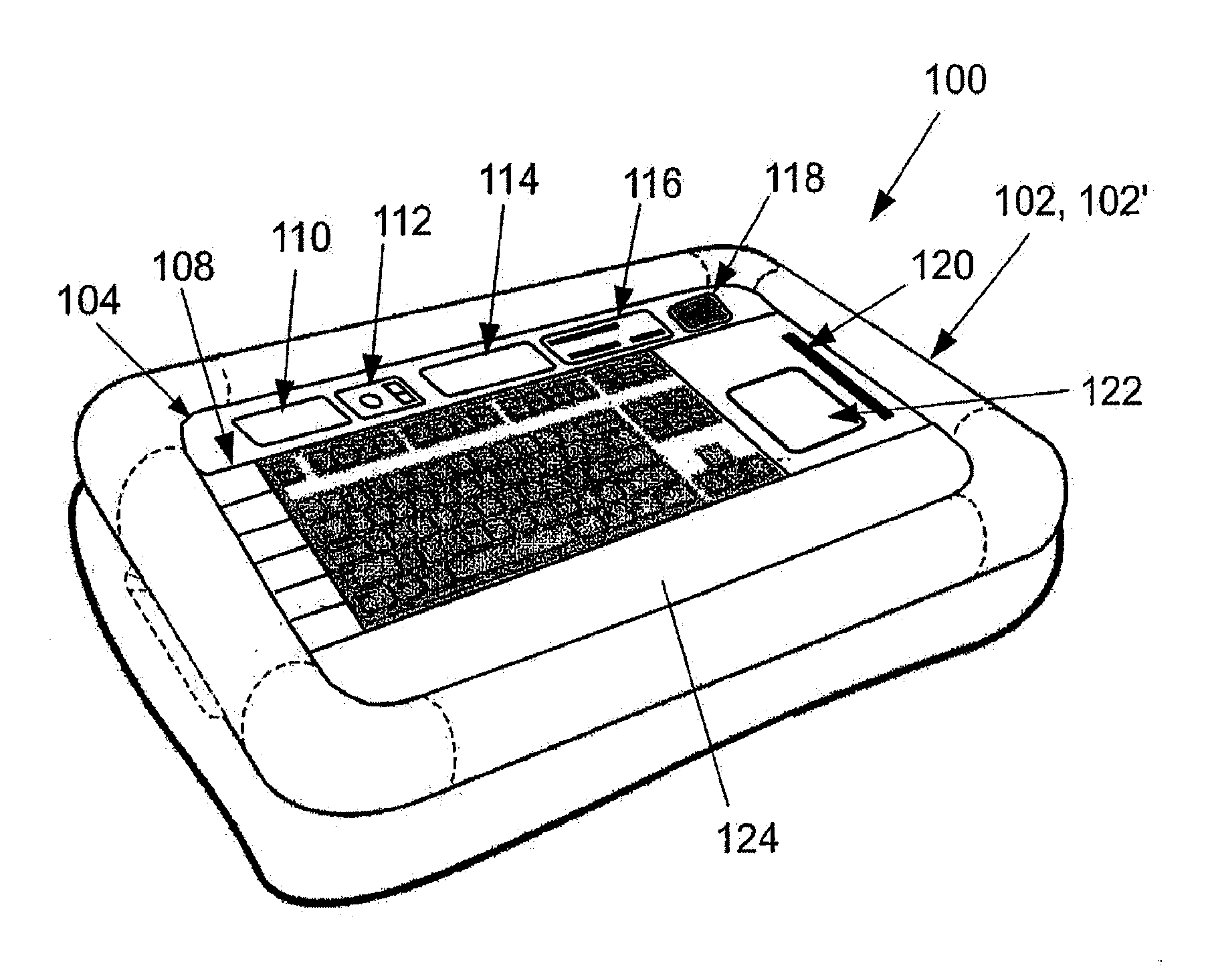
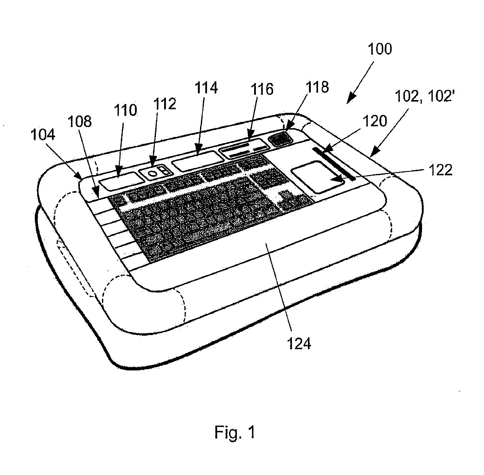
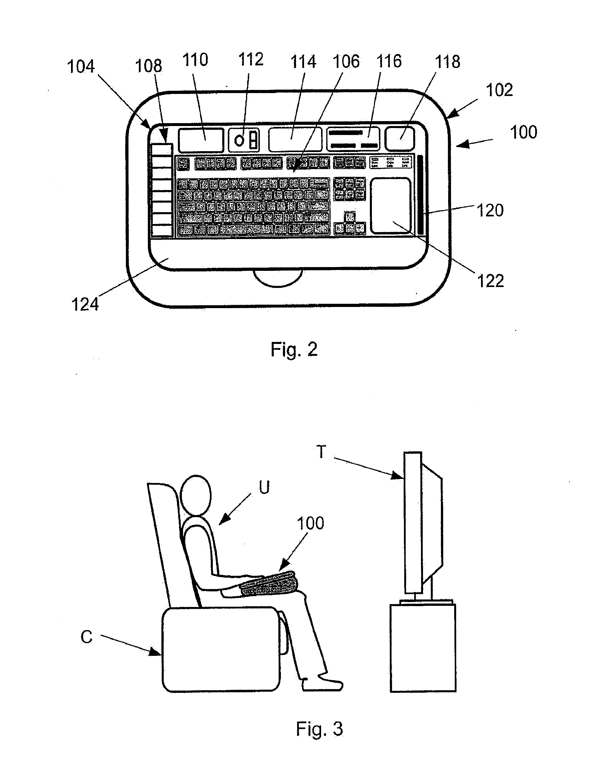
[0067]As shown in FIGS. 1 and 2, a user interface or control device in accordance with the present invention, shown generally at 100, generally includes a resilient or cushioned support member 102 in combination with an input member that enables a user to control or interact with another device. In FIGS. 1 and 2, the input member is in the form of a fully functioned keyboard assembly 104, which includes a keypad 106, a set of device actuation keys or buttons 108, an audio speaker 110, a camera 112, and the docking station or synchronizing cradle 114, a memory card or disc reader 116, an identification device 118 such as a fingerprint scanner, a card scanner at 120 such as for use in scanning credit cards or game cards, and a mouse-type touch pad 122. A wrist rest area 124 extends along one side of the keyboard assembly 104, for use in supporting a user's wrists when using keypad 106, in a manner as is known.

[0068]In a manner that will be more fully explained, user interface or contr...


PUM


Abstract

A user interface or control includes a cushion-type support member and a user input member that is interconnected with and carried by the support member. The support member defines an upwardly facing recess, and the input member may be a user interface or control device that is contained within the upwardly facing recess. The support member may be formed to surround the recess about the user interface or control device. The support member may include an air vent that vents air exhausted from the user interface or control device. The user interface or control device may be a laptop computer having a body including a keyboard contained within the recess, and a screen carried by the body. The user interface or control device may alternatively be an electronic input member having an upwardly facing screen, a convertible input member movably mounted to a mounting member, or a game controller.

Description

CROSS-REFERENCE TO RELATED APPLICATION[0001]This application claims the benefit of U.S. Provisional Application Ser. No. 60 / 883,614, filed Jan. 5, 2007, and U.S. Provisional Application Ser. No. 60 / 884,102, filed Jan. 9, 2007.BACKGROUND AND SUMMARY[0002]The present invention relates to a user interface or control device, and more particularly to a user interface or control device that can be comfortably and conveniently used by a user in numerous positions and for a variety of applications.[0003]User interface or control devices are used for many purposes. In some applications, a user interface or control device is a peripheral component that allows a user to interact with another device, such as a desktop computer, a remote monitor, a central server, etc. In other applications, a user may interact directly with the interface or control device. Examples of the latter include laptop computers, digital sketch boards, digital game boards, etc.[0004]Increasingly, user interface or contr...

Claims


Application Information

Patent Timeline
Patent Type & Authority Applications(United States)
IPC IPC(8): G06F3/02G06F1/16
CPCG06F3/0202G06F3/021G06F3/0208G06F3/033
Inventor SCHNEIDER, PAUL W.
Owner SCHNEIDER PAUL W
Why Eureka
Eureka Blog
Learn More