
Image processing device and method, image processing system, and image processing program

a technology of image processing which is applied in the field of image processing device and method, image processing system, and image processing program, can solve the problems of poor visual information, inability to identify moving objects, and difficulty in keeping track of the positional relation among all the moving objects within images generated by respective cameras

Active Publication Date: 2010-06-10
SONY CORP
View PDF5 Cites 63 Cited by
  • Summary
  • Abstract
  • Description
  • Claims
  • Application Information

AI Technical Summary

Benefits of technology

[0009]It is therefore desirable to use the display screen effectively while making it easier for the user to recognize respective moving objects in the tracking and displaying processing for a plurality of moving objects.
[0014]According to the embodiments of the present invention, the user becomes able to obtain detailed images of the tracking subjects that have not been obtained by the wide angle imaging while keeping track of the positional relation among the tracking subjects in the entire image display window. According to the embodiments of the present invention, in a case where the relative distances between the respective tracking subjects are equal to or smaller than the predetermined threshold value, the user becomes able to track a plurality of the tracking subjects as a group by displaying all the tracking subjects in one cutout image display window. According to the embodiments of the invention, even in a case where the relative distances among a plurality of the respective tracking subjects are larger than the predetermined value, by displaying two cutout images including the respective tracking subjects in the cutout image display window, the user becomes able to keep track of a detailed image for each of a plurality of the tracking subjects.
[0015]As has been described, according to the embodiments of the present invention, even when there are a large number of tracking subjects, the user becomes able to keep track of the tracking subjects precisely according to the positional relation among the tracking subjects displayed in the entire image display window.

Problems solved by technology

In this case, however, it is quite difficult to keep track of the positional relation among all the moving objects within images generated by the respective cameras.
The radar system, however, provides poor visual information and is therefore not suitable to identify a moving object.
It is therefore difficult to track a plurality of moving objects precisely.
It thus becomes difficult to use the display screen effectively.

Method used


Image

  • Image processing device and method, image processing system, and image processing program
  • Image processing device and method, image processing system, and image processing program
  • Image processing device and method, image processing system, and image processing program

Examples


Embodiment Construction

[0040]Hereinafter, concrete embodiments to which the present invention is applied will be described in detail with reference to the drawings.

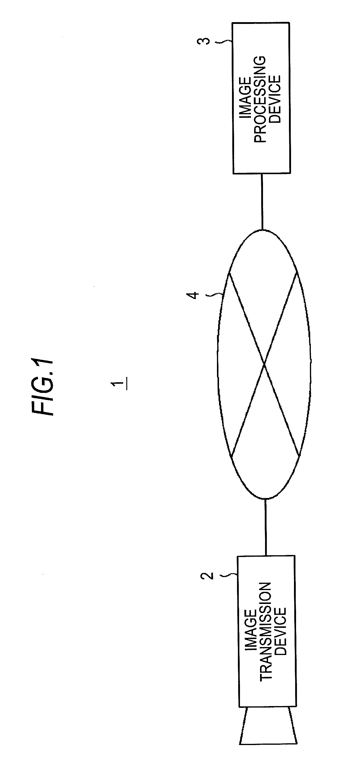
[0041]FIG. 1 is a view showing an image processing system 1 according to an embodiment to which the present invention is applied. The image processing system 1 includes an image transmission device 2 and an image processing device 3 connected to each other via a network 4, such as a LAN (Local Area Network) and the Internet.

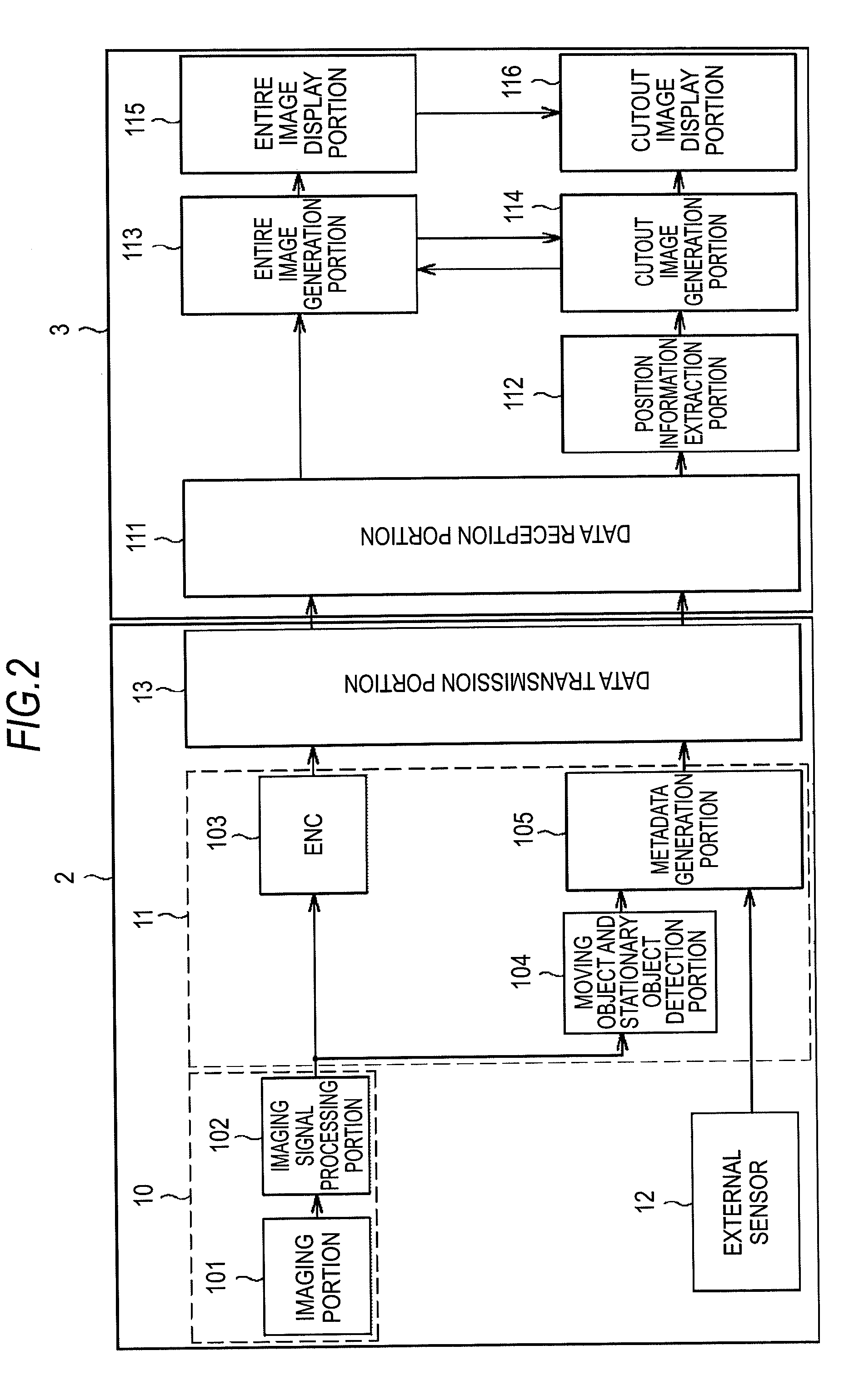
[0042]FIG. 2 is a view showing the internal configuration of the image transmission device 2 and the image processing device 3. The image transmission device 2 transmits an image signal generated from an imaging signal to the image processing device 3 via the network 4. The image processing device 3 applies predetermined signal processing to the image signal received from the image transmission device 2 via the network 4. Then, the image processing device 3 makes an entire image, which is an image of the imaging region, and ...


PUM


Abstract

An image processing device includes: an entire image display control portion that performs control to display an entire image of a predetermined region in an entire image display window; and a cutout image display control portion that performs control to enlarge a plurality of tracking subjects included in the entire image and display the tracking subjects in a cutout image display window. The cutout image display control portion performs the control in such a manner that one cutout image including the tracking subjects is displayed in the cutout image display window in a case where relative distances among the tracking subjects are equal to or smaller than a predetermined value, and that two cutout images including the respective tracking subjects are displayed in the cutout image display window in a case where the relative distances among the tracking subjects are larger than the predetermined value.

Description

BACKGROUND OF THE INVENTION[0001]1. Field of the Invention[0002]The present invention relates to image processing device and method, an image processing system, and an image processing program for tracking and displaying a plurality of moving objects.[0003]2. Description of Related Art[0004]There is an image processing system that displays a moving object by tracking the moving object using a monitoring camera or the like. JP-A-2006-121261 describes a technique of calculating pan-tilt angle information of a swivel base on which is mounted a camera according to position information and height information of a moving object obtained from a GPS (Global Positioning System) and controlling the camera with the angle of the swivel base so as not to lose track of the moving object using the single camera. Also, a technique of tracking a plurality of moving objects is described in “Kakushindo-tsuki kasetsugunno sougosayounimotozuku fukusuutaishou tsuiseki”Computer Vision and Image Media vol....

Claims


Application Information

Patent Timeline
Patent Type & Authority Applications(United States)
IPC IPC(8): H04N5/225G09G5/00
CPCG01S3/7864G08B13/1961H04N5/232G01S11/12H04N5/23238H04N5/2628G06K9/00624H04N5/23216H04N23/61H04N23/62H04N23/698H04N23/63H04N23/695G06T7/246G06T2207/10004
Inventor INAGUMA, RITSUOUJISATO, TAKANOBU
Owner SONY CORP
Learn More