Substrate holder, stage apparatus, and exposure apparatus with first support part provided in a suction space and second support part

a stage apparatus and substrate technology, applied in the direction of photomechanical treatment, instruments, printing, etc., can solve the problems of troublesome alignment, increased warpage (waviness) of the substrate, and difficulty in compensating for waviness using the stage drive, etc., to achieve stable and satisfactory flatness, and high resolution pattern

Inactive Publication Date: 2010-06-10
NIKON CORP
View PDF11 Cites 5 Cited by
  • Summary
  • Abstract
  • Description
  • Claims
  • Application Information

AI Technical Summary

Benefits of technology

[0016]Accordingly, with the substrate holder of the present invention, the second support part is linear (a projection) from the circumferential edge part to the first support part and supports the substrate at the circumferential edge part, which makes it possible to suppress waviness and warpage that occurs between the circumferential edge part (33) and the first support part.
[0018]Accordingly, with the stage apparatus of the present invention, it is possible to hold the substrate and move it to a prescribed position without causing major waviness or warpage of the substrate at the circumferential edge part of the substrate holder.
[0020]Accordingly, with the exposure apparatus of the present invention, the substrate can be moved without causing major waviness or warpage of the substrate at the circumferential edge part of the substrate holder, which makes it possible to transfer the pattern to the substrate with a prescribed transfer accuracy.
[0022]The present invention can support a substrate with a stable and satisfactory flatness, and can therefore form a high resolution pattern thereon.
[0023]In addition, when performing an exposure by using a liquid, the present invention prevents the infiltration of the liquid between the substrate and the substrate holder, which makes it possible to stably perform the exposure process.

Problems solved by technology

In addition, with this type of substrate holder, the suction force applied by the suction apparatus to negatively pressurize the suction chamber acts upon the inner flat surface of the wafer, but not upon its outer circumferential part, which causes such to warp even when using a wafer that has satisfactory flatness.
Nevertheless, the related art discussed above has the following types of problems.
When forming the suction groove in the outer circumferential wall, there is a problem in that it is necessary to strictly control the size of the suction groove in order to control the force that prevents warpage, which makes alignment troublesome.
In addition, there is also a concern that when liquid is filled between the wafer and the projection optical system and a pattern is exposed on the wafer through this liquid, i.e., when so-called immersion exposure is performed, the liquid will infiltrate the suction chamber from the suction groove.
In addition, to reduce the effect of dust located between the wafer and the support pins, the size of the upper surfaces of the support pins have shrunk in recent years, thereby creating a tendency for the support pin tips to bite into the rear surface of the wafer, which in turn tends to increase warpage (waviness) of the wafer between the location of the wafer that is supported by the outer circumferential wall and the location that is supported by the support pins.
Waviness of an exposure slit (a slit through which exposure illumination light is projected), which is for transferring the pattern to the wafer, is compensated for by correcting the position of the wafer front surface by driving (e.g., leveling) a wafer stage so that the flatness of the slit is within a prescribed value; however, compensating for waviness using the stage drive is problematic because, for example, waviness increases if the exposure slit is at a position where it straddles the outer circumferential wall.

Method used


Image

  • Substrate holder, stage apparatus, and exposure apparatus with first support part provided in a suction space and second support  part
  • Substrate holder, stage apparatus, and exposure apparatus with first support part provided in a suction space and second support  part
  • Substrate holder, stage apparatus, and exposure apparatus with first support part provided in a suction space and second support  part

Examples


first embodiment

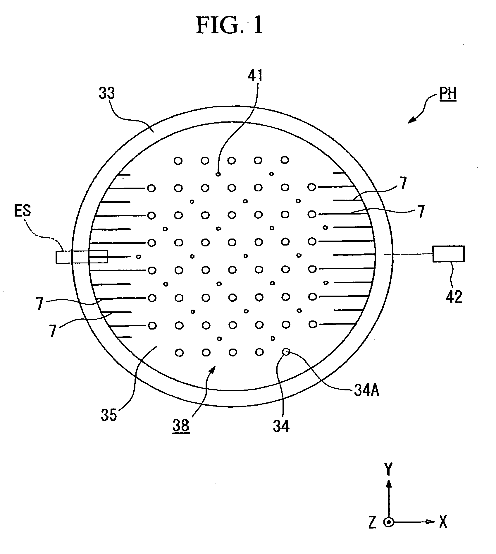
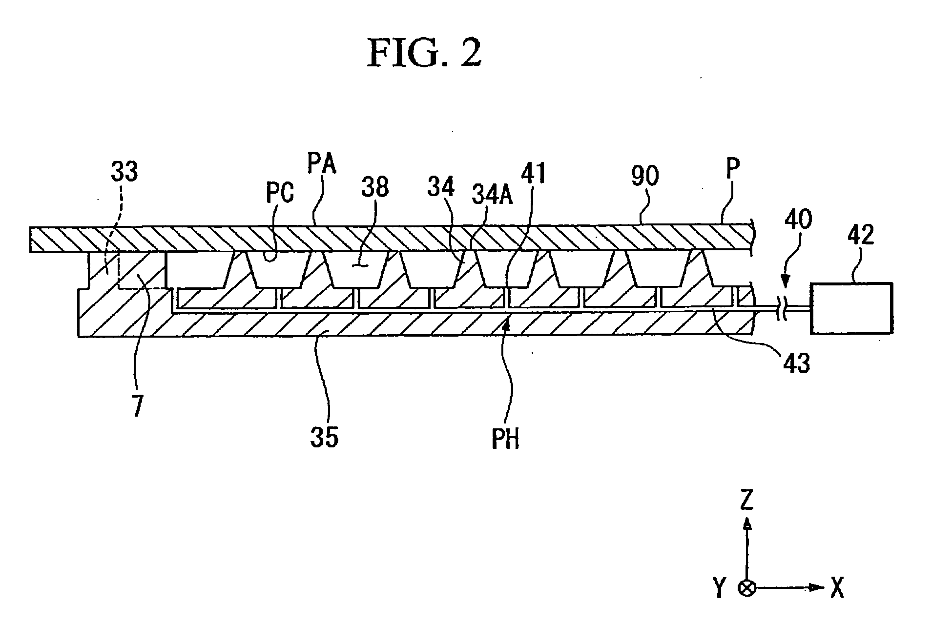
[0034]First, the substrate holder according to the present invention will be explained, referencing FIG. 1 and FIG. 2. FIG. 1 is a plan view of the substrate holder and FIG. 2 is a partially enlarged view that shows the substrate holder holding a substrate P.

[0035]A substrate holder PH vacuum chucks the substrate P and comprises: a substantially discoidal base part 35; a circumferential wall part 33 (circumferential edge part), which is provided along a circumferential edge of the base part 35 so that it is upright, that supports a rear surface PC of the substrate P on the inner side of the outer circumference of the substrate P; a plurality of support parts 34 (first support parts) that are evenly disposed in a suction space 38, which is on the inner side of and surrounded by the circumferential wall part 33, and that supports the substrate P; and a plurality of rib shaped support parts 7 (second support parts), which extend from the circumferential wall part 33 toward the support ...

second embodiment

[0044]Continuing, the substrate holder according to the present invention will now be explained, referencing FIG. 3.

[0045]Constituent elements in this figure that are the same as those in the first embodiment shown in FIG. 1 and FIG. 2 are assigned the same symbols.

[0046]In the substrate holder PH according to the second embodiment, rib shaped support parts 7A, which support the substrate P, are provided radially; furthermore, one end of each of the rib shaped support parts 7A is connected to the circumferential wall part 33, and the other end of each extends toward the support parts 34. The support surface area wherein these rib shaped support parts 7A support the substrate P is also set larger than the support surface area wherein the support parts 34 supports the substrate P. In addition, in the present embodiment as well, the lengths of at least adjacent rib shaped support parts 7A, which extend toward the support parts 34, vary. Other aspects of the constitution of the present ...


PUM


Abstract

An object of the invention is to hold a substrate with satisfactory flatness, even at a circumferential edge part that surrounds a suction space. The invention is equipped with a circumferential edge part that surrounds a suction space, and a first support part that is provided in the suction space and that supports a substrate. Furthermore, the invention is equipped with a second support part that extends from the circumferential edge part to the first support part and that supports the substrate.

Description

[0001]This is a Continuation of application Ser. No. 11 / 611,372 filed Feb. 28, 2007, which is a National Phase of PCT / JP2005 / 015687 filed Aug. 29, 2005. The disclosure of the prior applications are hereby incorporated by reference herein in their entirety.BACKGROUND[0002]The present invention relates to a substrate holder, a stage apparatus, and an exposure apparatus, and more particularly relates to, for example, a substrate holder and a stage apparatus that are ideal for vacuum chucking a substrate, such as a wafer, as well as an exposure apparatus that comprises this substrate holder.[0003]The disclosure of the following priority application is hereby incorporated by reference in its entirety: Japanese Patent Application No. 2004-253978, which was filed on Sep. 1, 2004.[0004]Projection type exposure apparatuses and laser repair apparatuses are known examples of apparatuses that fabricate, for example, semiconductor wafers (hereinbelow, called wafers) used in the manufacture of se...

Claims


Application Information

Patent Timeline
Patent Type & Authority Applications(United States)
IPC IPC(8): G03B27/58
CPCG03F7/707H01L21/6875H01L21/6838G03F7/70808
Inventor SHIBAZAKI, YUICHI
Owner NIKON CORP
Why Eureka
Try Eureka