
Visual cryptography and voting technology

a cryptography and visual technology, applied in the field of security, can solve the problems of poor quality of reconstructed ballot images, lack of voter verification audit trail, and lack of adequate defenses of current voting technology against manipulation

Active Publication Date: 2010-06-10
ROSKIND JAMES A
View PDF10 Cites 8 Cited by
  • Summary
  • Abstract
  • Description
  • Claims
  • Application Information

AI Technical Summary

Problems solved by technology

Current voting technology does not provide adequate defenses against the manipulation of results, does not provide a voter-verifiable audit trail, suffers from poor quality in reconstructed ballot images, is susceptible to coercion, is vulnerable to malicious attacks and / or is cumbersome to use.
Existing visual cryptographic methods are difficult to align and construe, and provide poor grayscale rendering.

Method used


Image

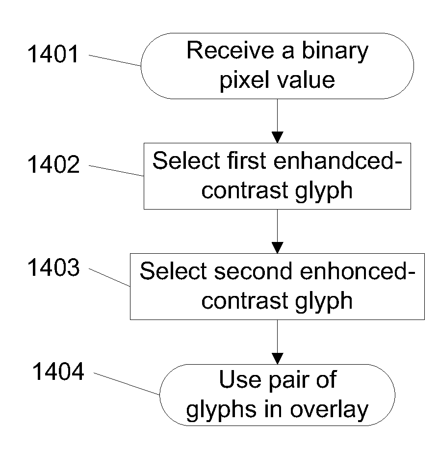
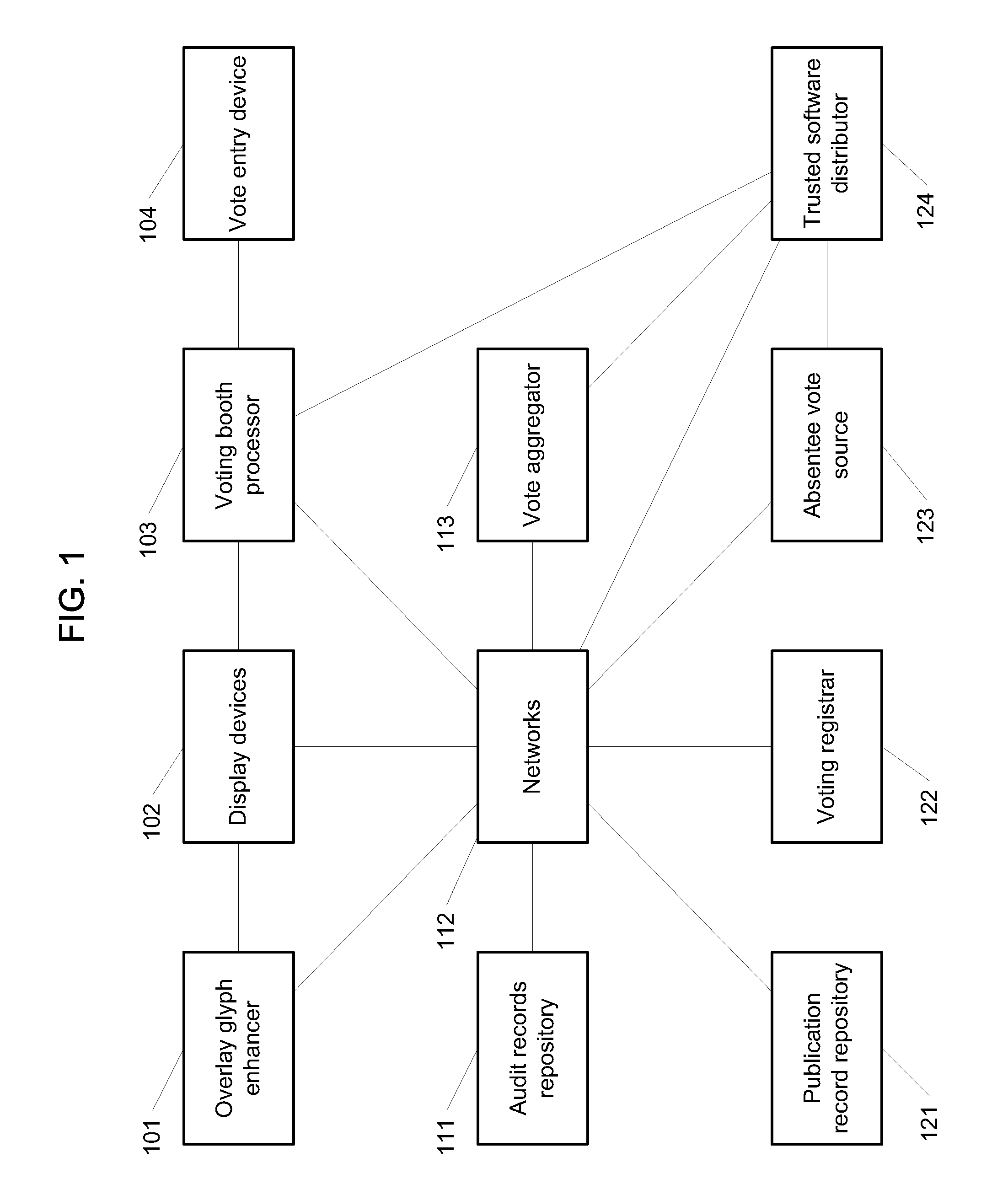
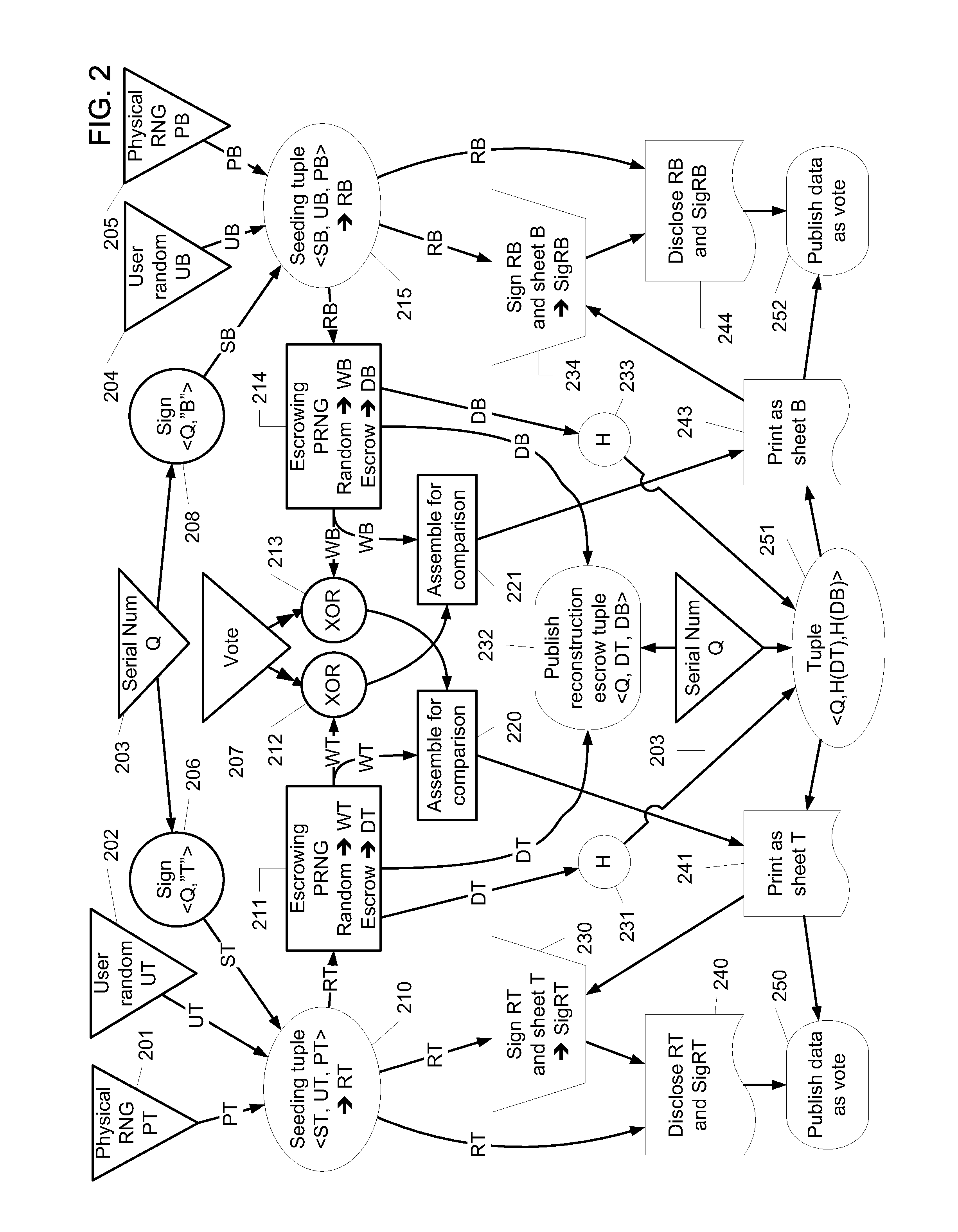
  • Visual cryptography and voting technology
  • Visual cryptography and voting technology
  • Visual cryptography and voting technology

Examples


Embodiment Construction

[0039]The invention can be implemented in numerous ways, including as a process, an apparatus, a system, a composition of matter, a computer readable medium such as a computer readable storage medium or a computer network wherein program instructions are sent over optical or electronic communication links. In this specification, these implementations, or any other form that the invention may take, may be referred to as techniques. In general, the order of the steps of disclosed processes may be altered within the scope of the invention.

[0040]A detailed description of one or more embodiments of the invention is provided below along with accompanying figures that illustrate the principles of the invention. The invention is described in connection with such embodiments, but the invention is not limited to any embodiment. The scope of the invention is limited only by the claims and the invention encompasses numerous alternatives, modifications and equivalents. Numerous specific details ...


PUM


Abstract

In some embodiments, techniques for voting and visual cryptography may include various enhancements.

Description

RELATED APPLICATIONS[0001]This application is a Continuation of Ser. No. 11 / 048,514 filed Jan. 31, 2005, which claims priority to U.S. Provisional Patent Application No. 60 / 540,723 filed Jan. 30, 2004, U.S. Provisional Patent Application No. 60 / 554,668 filed Mar. 18, 2004 and U.S. Provisional Patent Application No. 60 / 580,270 filed Jun. 16, 2004, which are incorporated herein by reference for all purposes.FIELD OF THE INVENTION[0002]The present invention relates generally to the area of security. More specifically, techniques for voting and visual cryptography are disclosed.BACKGROUND OF THE INVENTION[0003]Voting is used for a wide variety of applications, including political offices, corporate officers, and initiatives. Current voting technology does not provide adequate defenses against the manipulation of results, does not provide a voter-verifiable audit trail, suffers from poor quality in reconstructed ballot images, is susceptible to coercion, is vulnerable to malicious attack...

Claims


Application Information

Patent Timeline
Patent Type & Authority Applications(United States)
IPC IPC(8): G06K15/02H04N1/60G09C5/00
CPCG06F21/6254G09C5/00G06F2221/2107G06F2221/2101
Inventor ROSKIND, JAMES A.EMIGH, AARON T.
Owner ROSKIND JAMES A
Learn More