Method and apparatus for correcting depth image

a depth image and depth value technology, applied in image enhancement, color signal processing circuits, instruments, etc., can solve the problems of difficult to provide accurate depth values of real world objects, distortion of measured depth values, and complex process, and achieve the effect of convenient supplementing a correction function

Active Publication Date: 2010-06-10
SAMSUNG ELECTRONICS CO LTD
View PDF6 Cites 22 Cited by
  • Summary
  • Abstract
  • Description
  • Claims
  • Application Information

AI Technical Summary

Benefits of technology

[0009]Example embodiments may provide an apparatus for correcting a depth image that may correct a depth distortion for each color of an object, thereby generating a depth image corresponding to actual depth characteristics of the object.
[0010]Example embodiments may also provide an apparatus of correcting a depth image that may correct a distortion having different magnitudes for different depth cameras, thereby generating a depth image corresponding to actual depth characteristics of an object.
[0011]Example embodiments may further provide an apparatus of correcting a depth image that may maintain a table for correction, thereby easily supplementing a correction function even in a depth camera that does not have the correction function.

Problems solved by technology

The depth image may be passively extracted from several color images using computer vision techniques, however, this may have a complex process, and it is difficult to provide accurate depth values of real world objects.
However, the depth camera may measure a depth value based on a Time Of Flight (TOF), and thus a distortion of the measured depth value may occur due to characteristics of the object or a peripheral environment.

Method used


Image

  • Method and apparatus for correcting depth image
  • Method and apparatus for correcting depth image
  • Method and apparatus for correcting depth image

Examples


Embodiment Construction

[0020]Reference will now be made in detail to example embodiments, examples of which are illustrated in the accompanying drawings, wherein like reference numerals refer to the like elements throughout. Example embodiments are described below to explain the present disclosure by referring to the figures.

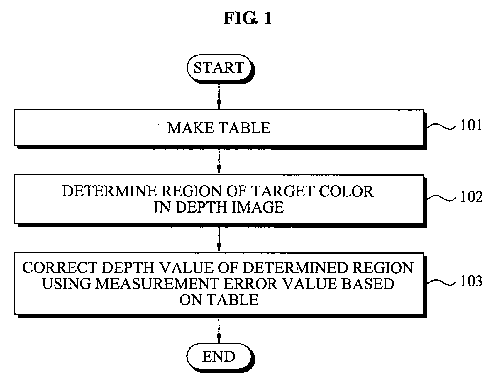
[0021]FIG. 1 illustrates a flowchart of a method for correcting a depth image in an apparatus for correcting the depth image according to example embodiments.

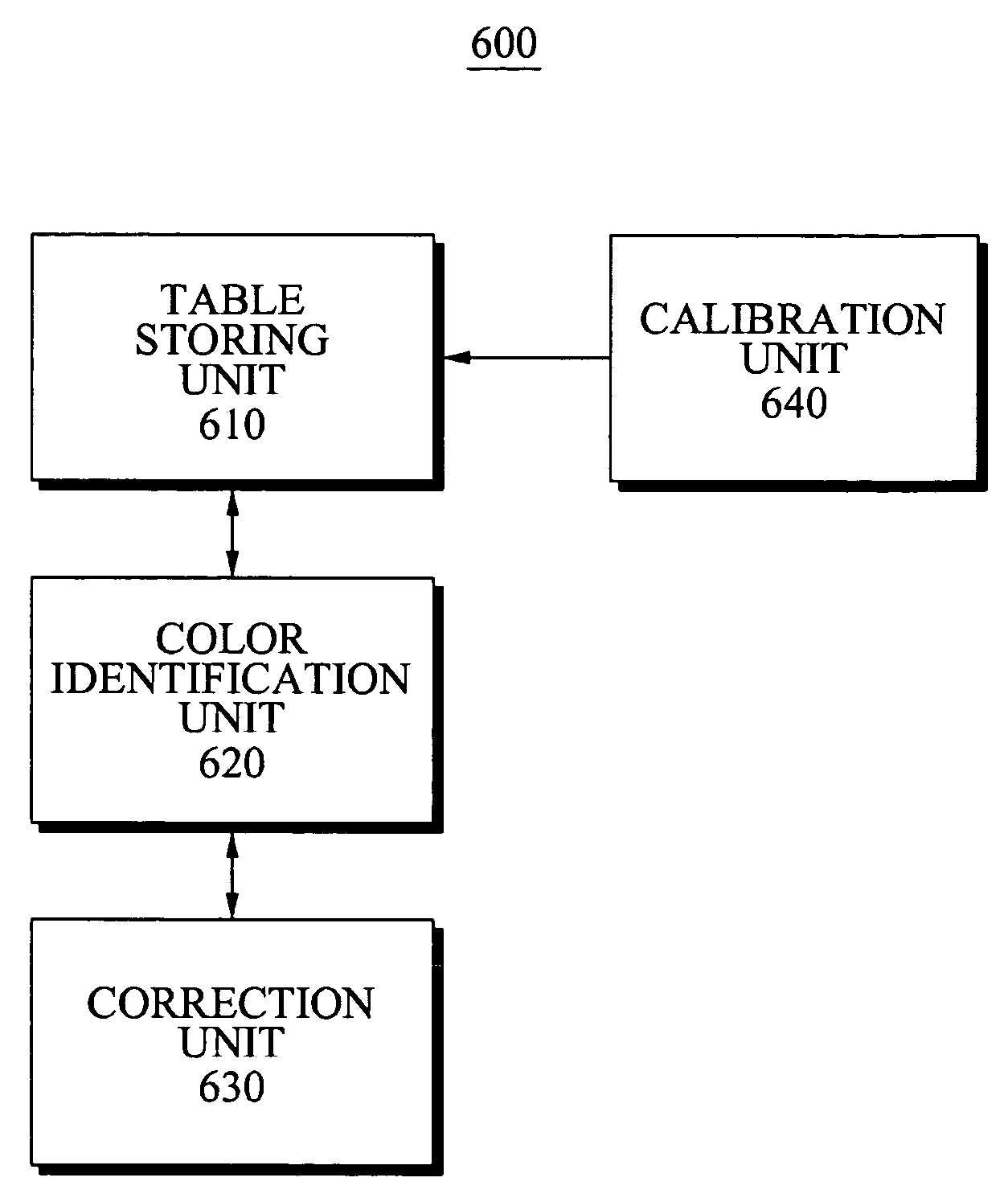
[0022]Referring to FIG. 1, in operation 101, the apparatus for correcting the depth image according to the present example embodiment may make a table formed according to color identification information of a target color and a measurement error corresponding to the color identification information

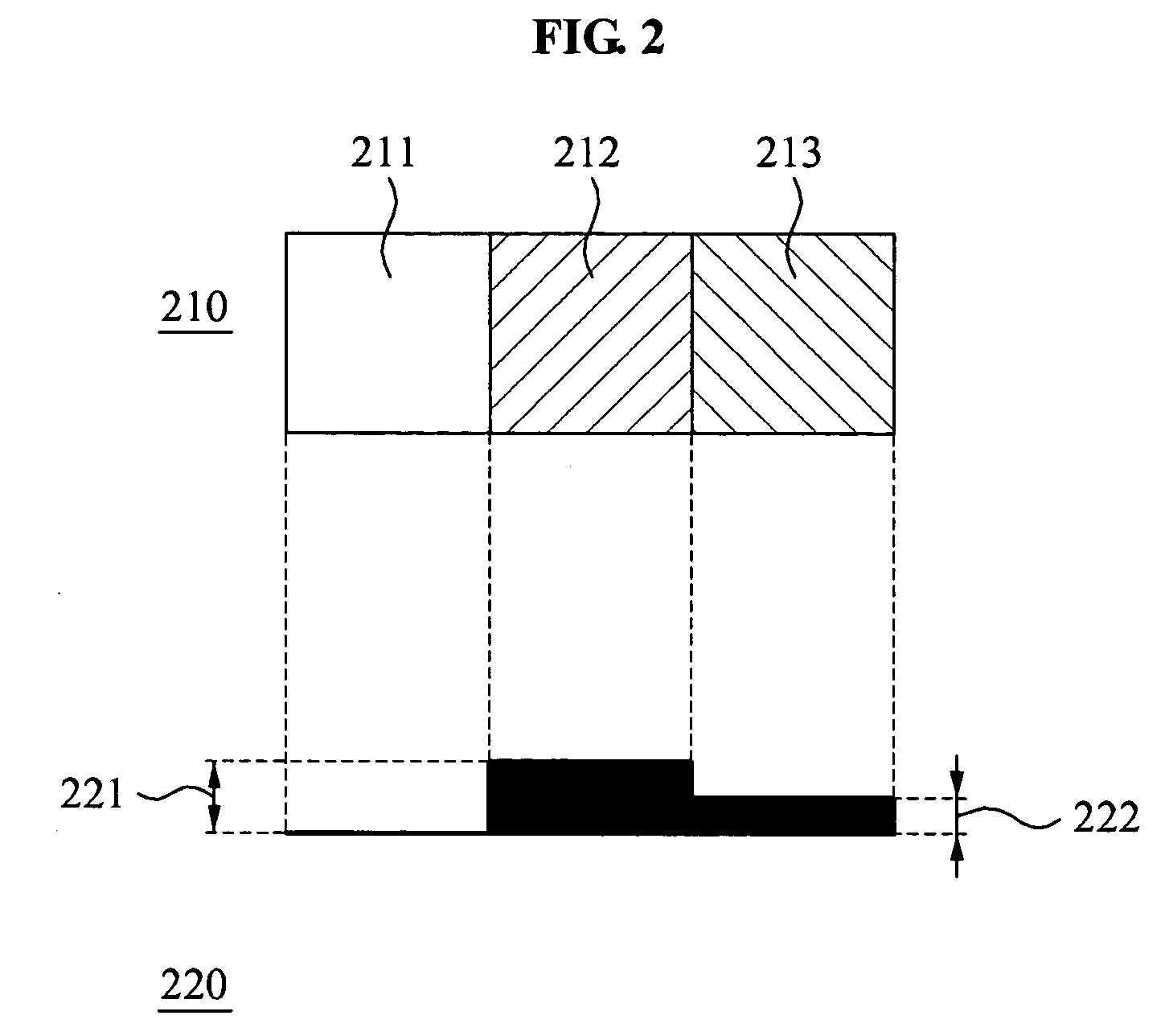
[0023]The target color may designate all colors other than the base color.

[0024]Also, the target color may be understood as a color having a depth value different from that of the base color although being positioned at the same distanc...


PUM


Abstract

An apparatus and method for correcting a depth image of an object based on a table, the table being formed according to color identification information of a target color, and a first measurement error in which a difference between a ground truth depth value of a base color and a measured depth value of the target color is reflected.

Description

CROSS-REFERENCE TO RELATED APPLICATIONS[0001]This application claims the benefit of Korean Patent Application No. 10-2008-0122440, filed on Dec. 4, 2008, in the Korean Intellectual Property Office, the disclosure of which is incorporated herein by reference.BACKGROUND[0002]1. Field[0003]Example embodiments of the following description relate to a method and apparatus for correcting a depth image that may correct distortion of a depth image of a depth camera based on a difference between a measured depth value associated with a target color and a ground truth depth value associated with a base color, thereby generating an accurate depth image realistically corresponding to an object.[0004]2. Description of the Related Art[0005]Three-dimensional (3D) information may be utilized in various application fields. In general, the 3D information may include geometry information and color information. The color information may be obtained in a color image type using an image acquisition appar...

Claims


Application Information

Patent Timeline
Patent Type & Authority Applications(United States)
IPC IPC(8): G06K9/00
CPCG01S7/497G06T7/0018G06T7/0051H04N13/0257G06T2207/10028H04N13/0003H04N13/0037G06T2207/10024H04N2013/0081G06T7/80G06T7/50H04N13/257H04N13/271H04N13/10H04N13/15H04N13/128H04N9/64H04N13/00H04N23/10
Inventor SIM, JAE YOUNG
Owner SAMSUNG ELECTRONICS CO LTD
Why Eureka
Try Eureka