Speed controlled strength machine

a speed control and strength machine technology, applied in the field of exercise apparatus, can solve the problems of long learning curve, low back stress and fatigue, and inability to fully reproduce the experience with sufficient accuracy to provide many health benefits of natural exercis

Inactive Publication Date: 2010-06-10
SCHMIDT DAVID H
View PDF51 Cites 82 Cited by
  • Summary
  • Abstract
  • Description
  • Claims
  • Application Information

AI Technical Summary

Problems solved by technology

Although various attempts have been made to simulate cross-country ski exercise or other bilateral exercise on a stationary exercise machine, these attempts have not been fully successful in reproducing the experience with sufficient accuracy to provide many of the health benefits of natural exercise.
It is believed that in such (stationary) machines, pushing against the abdominal pad can lead to lower back stress and fatigue and detracts from an accurate simulation of the natural cross-country ski exercise.
It is further believed that the lack of forward resistance and the associated lack of balance in such devices lead to a long learning curve such that, to successfully use the machine, a user must develop a new technique for walking or skiing which is very different from that found in nature.
Again, it is believed that many stationary exercise devices fail to reproduce this feature of the natural exercise with sufficient accuracy to provide an enjoyable exercise experience and to provide all the benefits available with natural exercise, such as a more natural and less stressful distribution of force on the joints and development of good balance.
Many types of previous exercise devices have failed to provide a completely satisfactory simulation of natural upper body exercise.
Thus it was impossible to accurately simulate double poling or poling with a single arm.
In such devices, if an exerciser was expending a given level of effort, by exerting greater upper body efforts, the user was not, thereby, permitted to correspondingly decrease...

Method used


Image

  • Speed controlled strength machine
  • Speed controlled strength machine
  • Speed controlled strength machine

Examples


Embodiment Construction

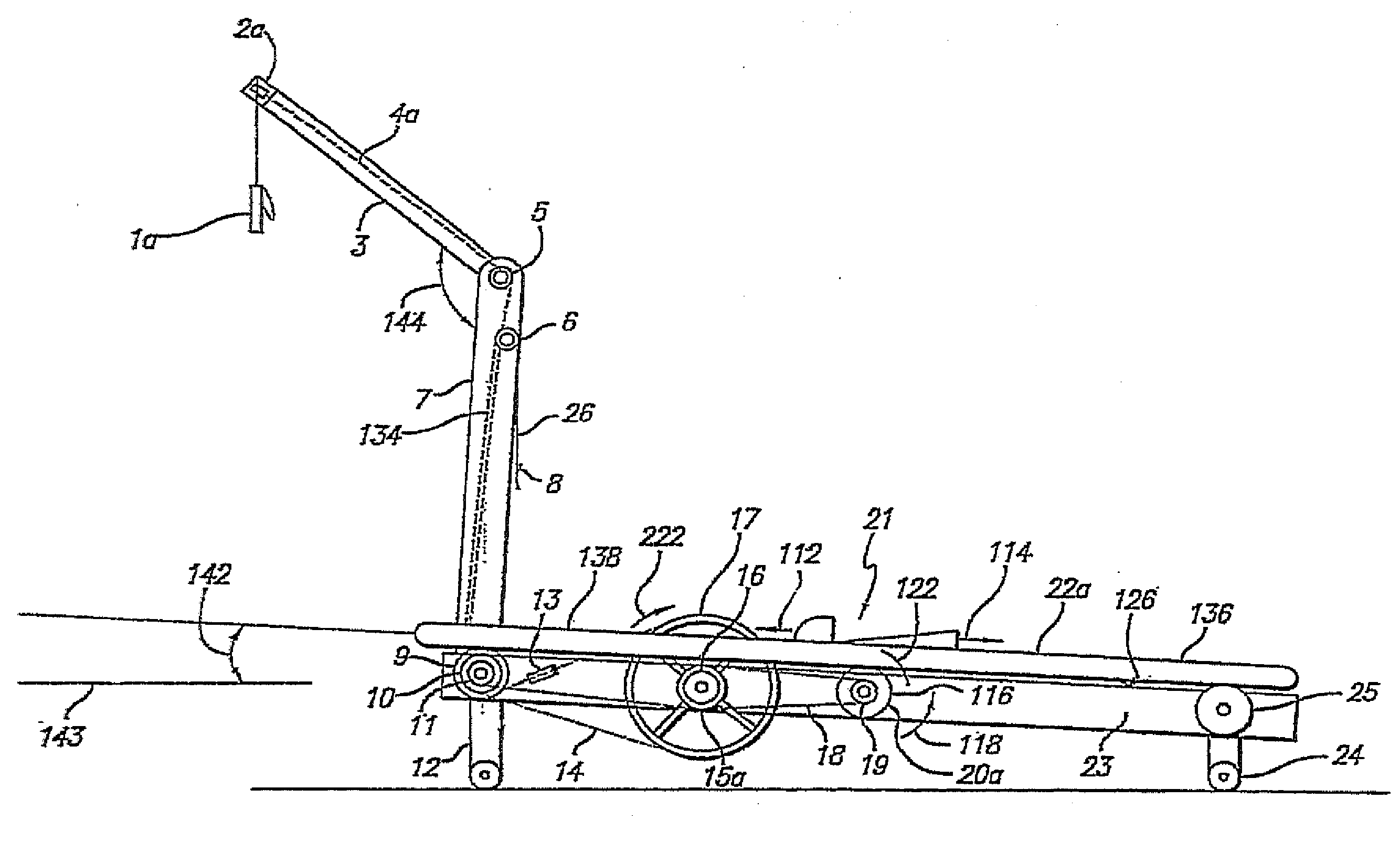
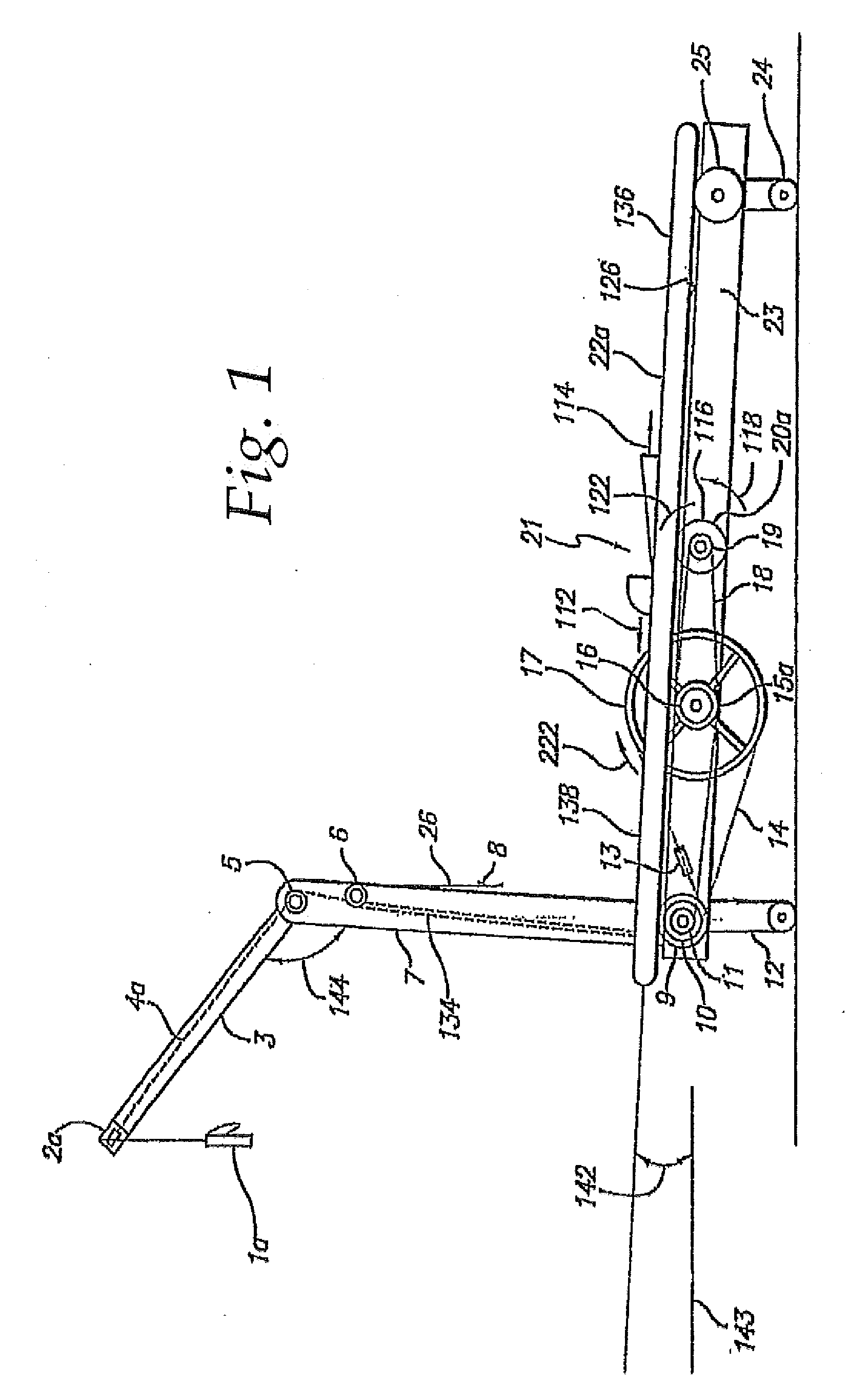
[0077]As seen in FIG. 1, according to one embodiment, an exercise device includes a lower frame member, 23 supported by front and rear frame supports 12, 24. The frame members, support members and the like can be made of a number of materials, including metal, such as steel or aluminum, plastic, fiberglass, wood, reinforced and / or composite materials, ceramics and the like. Preferably the frame supports 12, 24 are coupled to the lower frame such that the lower frame can be inclined 142 at various angles. For example, the incline of the machine can be adjusted by providing front supports 12 with various adjustment mechanisms such as a rack-and-pinion adjustment, hole-and-pin adjustment, ratchet adjustment, and the like. The machine can be operated at an inclination 142 within any of a range of angles, such as between about 2 degrees and 45 degrees (or more) to the horizontal 143. Preferably, in the embodiment of FIG. 1, at least some upward inclination 142 is provided during use, e.g...


PUM


Abstract

A speed controlled strength machine is provided. The machine includes a frame and a number of support members. A driver is mounted to the frame and includes an adjustable speed controller. During exercise, the user engages grips/handles and pulls them via one-way clutches through the resistive movement of the driver. The clutches are engaged when the user is able to reach a predetermined speed, which is adjustable and controllable.

Description

CROSS-REFERENCE TO RELATED APPLICATIONS[0001]This application claims benefit as a continuation-in-part of application Ser. No. 12 / 420,928, filed Apr. 19, 2009, which claims benefit as a continuation of application Ser. No. 10 / 685,625 filed Oct. 15, 2003, now U.S. Pat. No. 7,179,205, which claims benefit under: (i) 35 U.S.C. 119(e) of U.S. Provisional Application, Ser. No. 60 / 418,461 filed Oct. 15, 2002; and (ii) as a Continuation-In-Part of application Ser. No. 09 / 977,123 filed Oct. 12, 2001, now U.S. Pat. No. 6,835,167, which is a continuation of application Ser. No. 08 / 865,235 filed May 29, 1997, now U.S. Pat. No. 6,302,829, which claims benefit of application Ser. No. 60 / 018,755 filed May 31, 1996.BACKGROUND OF THE INVENTION[0002]The present invention relates to an apparatus for performing exercise and a method for using such apparatus and in particular to an apparatus which closely simulates many natural forms of exercise such as cross-country skiing, walking, running, biking, c...

Claims


Application Information

Patent Timeline
IPC IPC(8): A63B22/04
CPCA63B21/012A63B21/00069A63B21/153A63B21/157A63B21/225A63B22/0012A63B22/0023A63B22/02A63B22/0242A63B22/0605A63B22/20A63B22/203A63B23/03541A63B23/12A63B23/1281A63B69/06A63B69/16A63B69/182A63B71/0054A63B2022/0017A63B2022/0038A63B2022/0041A63B2024/0068A63B2024/0093A63B2071/025A63B2071/063A63B2220/13A63B2220/30A63B2220/51A63B22/205A63B21/015A63B21/00196A63B21/0058A63B21/078A63B21/154A63B23/03525A63B23/03533A63B23/1209A63B71/0619A63B2220/17A63B2220/20A63B2220/803A63B2220/805A63B21/4035A63B21/4043A63B22/0017
Inventor SCHMIDT, DAVID H.
Owner SCHMIDT DAVID H
Why Eureka
Try Eureka