Method and device for cleaning of a fluid in a centrifugal separator

a centrifugal separator and fluid cleaning technology, applied in the direction of centrifugal force sediment separation, centrifugal force separation, separation processes, etc., can solve the problems of affecting the degree of separation and rendering continued separation impossible, and achieve the effect of improving the degree of separation of the fluid

Active Publication Date: 2010-06-10
ALFA LAVAL CORP AB
View PDF38 Cites 12 Cited by
  • Summary
  • Abstract
  • Description
  • Claims
  • Application Information

AI Technical Summary

Benefits of technology

[0005]One object of the present invention is to provide a simple device for improving the degree of separation of the fluid.

Problems solved by technology

A problem with the purifying of oil according to the prior art is that some of the particles separated from the oil deposit themselves, together with separation aid, on the inside of the rotor in the form of a highly viscous layer of separated particles and separation aid.
This layer of separated particles constitutes a relatively solid sludge phase which grows radially inwards towards the axis of rotation, impairing the degree of separation and ultimately rendering continued separation impossible because of obstruction.

Method used


Image

  • Method and device for cleaning of a fluid in a centrifugal separator
  • Method and device for cleaning of a fluid in a centrifugal separator
  • Method and device for cleaning of a fluid in a centrifugal separator

Examples


Embodiment Construction

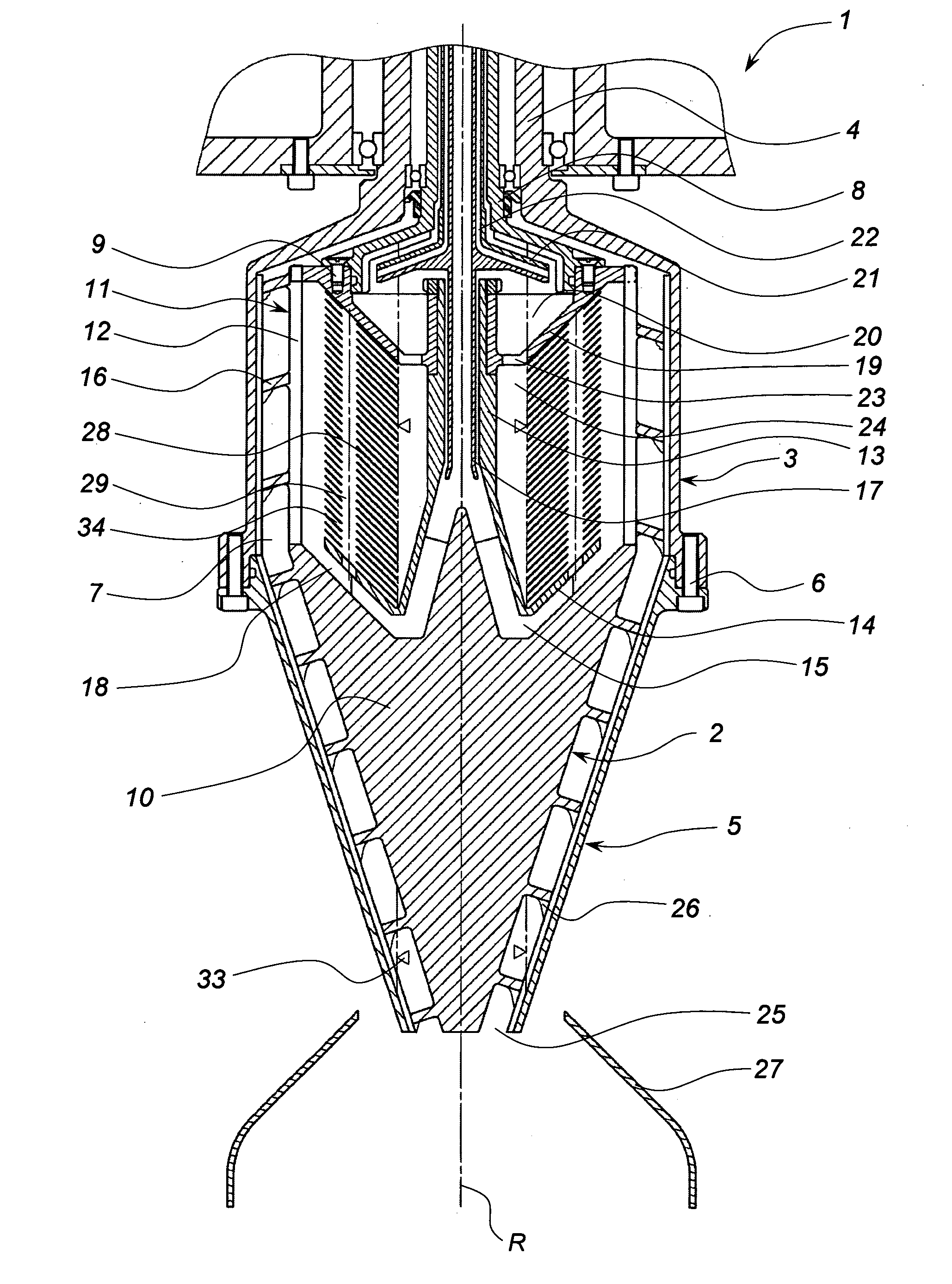
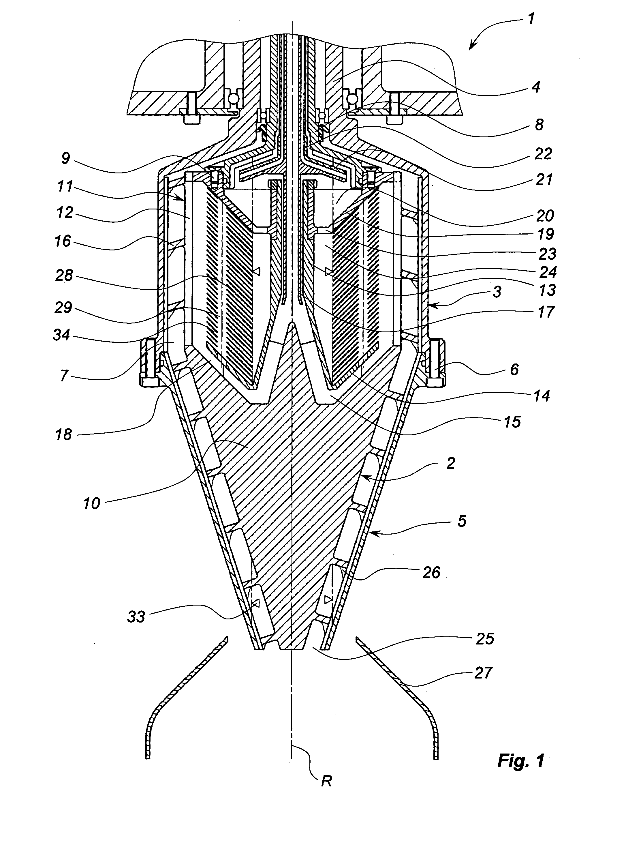
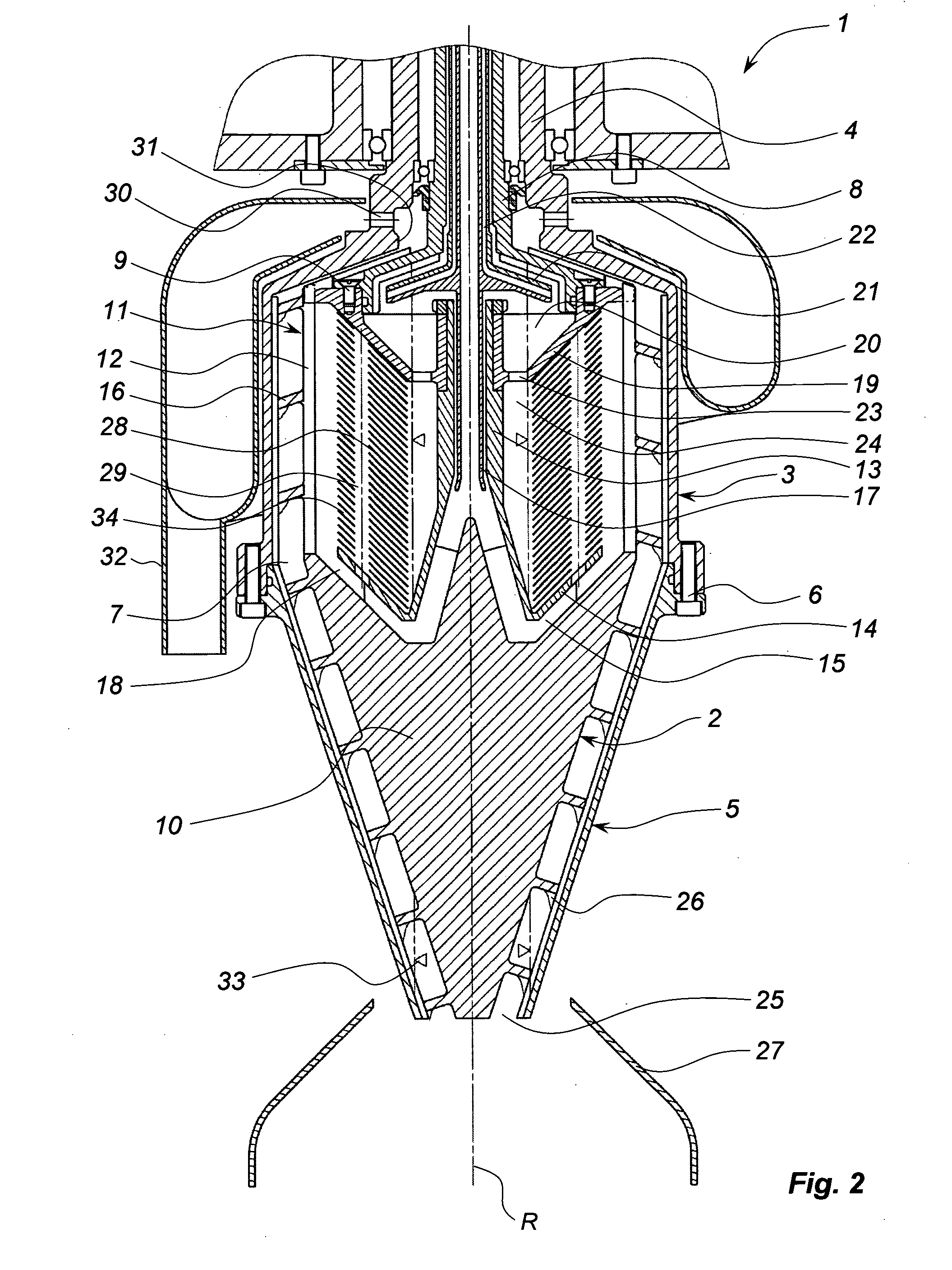
[0014]FIG. 1 discloses an example of a centrifugal separator comprising a rotor body 1 which is rotatable at a certain speed about a vertical axis of rotation R, and a screw conveyor 2 which is arranged in the rotor body 1 and rotatable about the same axis of rotation R but at a speed which differs from the rotation speed of the rotor body 1.

[0015]The centrifugal separator is intended to be suspended vertically in a manner indicated by WO 99 / 65610. The device necessary for suspending and driving the centrifugal separator is therefore not described here.

[0016]The rotor body 1 has an essentially cylindrical upper rotor portion 3 comprising or connected to a hollow rotor shaft 4, and an essentially conical lower rotor portion 5. The rotor portions 3 and 5 are connected to one another by screws 6 and delimit a separation chamber 7. Alternative connecting arrangements may also be used.

[0017]A shaft 8, shown in the illustrated embodiment as being hollow, extends into the rotor body 1 via ...


PUM

PropertyMeasurementUnit
Centrifugal forceaaaaaaaaaa
Flow rateaaaaaaaaaa
Densityaaaaaaaaaa

Abstract

A method for purifying a fluid from contaminating particles in a centrifugal separator by means of a separation aid which is of higher density than the fluid and which binds said particles, the centrifugal separator having a rotor body that rotates about an axis of rotation. The fluid to be purified is led via an inlet into a separation chamber delimited by the rotor body. Separated particles are discharged via a first outlet and clarified fluid cleared is discharged via a second outlet. The fluid being mixed with an amount of separation aid, supplied to the separation chamber. The pollutant particles are bound to the separation aid, which is forced out by the rotation of the rotor body to the periphery thereof. A small flow of separation aid and particles bound thereto are discharged from the separation chamber via the first outlet, and a flow of purified fluid is discharged from the separation chamber via the second outlet.

Description

FIELD OF THE INVENTION[0001]The present invention relates to an apparatus and method for purifying a fluid, in which the fluid is purified of contaminating particles in a centrifugal separator by means of a separation aid which is of higher density than the fluid and which binds these particles.BACKGROUND TO THE INVENTION[0002]WO 2004 / 053035 discloses a device in the form of a centrifugal separator for purifying an oil from particles. For the purification of the oil, a separation aid which binds the particles is added and thereby increases the degree of separation compared with using only the rotation of the rotor.[0003]A problem with the purifying of oil according to the prior art is that some of the particles separated from the oil deposit themselves, together with separation aid, on the inside of the rotor in the form of a highly viscous layer of separated particles and separation aid. This layer of separated particles constitutes a relatively solid sludge phase which grows radia...

Claims


Application Information

Patent Timeline
IPC IPC(8): B04B1/20B04B1/08
CPCB04B1/08B04B1/20B04B2001/2066C10G2300/308C10M175/0058C10G2300/1062C10G2300/201C10G31/10
Inventor RIDDERSTRALE, ROLFWASE, CLAES
Owner ALFA LAVAL CORP AB
Why Eureka
Try Eureka