U-shaped iron core transporting/assembling method, and u-shaped iron core transporting/assembling tank

a technology of transporting/assembling and iron core, which is applied in the direction of magnetic bodies, magnetic core manufacturing, instruments, etc., can solve the problems of installation cost, wasting more time on the installation of the entire transformer, and reducing the installation period.

Inactive Publication Date: 2010-06-17
KK TOSHIBA
View PDF4 Cites 4 Cited by
  • Summary
  • Abstract
  • Description
  • Claims
  • Application Information

AI Technical Summary

Benefits of technology

[0018]According to the present invention, in the case where the U-shaped iron core is transported in a disassembled condition, it is possible to reduce the installation period and installation cost by performing on-site assembly of the U-shaped iron core of a transformer, etc. in a U-shaped iron core transporting / assembling tank.

Problems solved by technology

However, the on-site iron core assembling method of the disassembled transportation transformer has the following problems.
Thus, it takes more time to install the entire transformer than in the case of a general disassembled transportation transformer where the iron core is transported in the form of the U-shaped iron core by the time length required for assembling the U-shaped iron core at the installation site.
For example, it is necessary to open the roof of the assembling room when the iron core is carried into the assembling room, so that the carry-in work cannot be performed in the case of rain, delaying the installation.
The rental fee, etc., of such a tow truck with large hoisting capacity is high, and there is no other way but to rent a tow truck whose per-unit time rental fee is high in order to assemble the U-shaped iron core, causing increase in cost.
When the roofs are opened, a large volume of external air is introduced inside the spare room and assembling room, so that it is necessary to perform dehumidification and dust removal every time the roofs are opened, which may cause delay of the installation.

Method used


Image

  • U-shaped iron core transporting/assembling method, and u-shaped iron core transporting/assembling tank
  • U-shaped iron core transporting/assembling method, and u-shaped iron core transporting/assembling tank
  • U-shaped iron core transporting/assembling method, and u-shaped iron core transporting/assembling tank

Examples


first embodiment

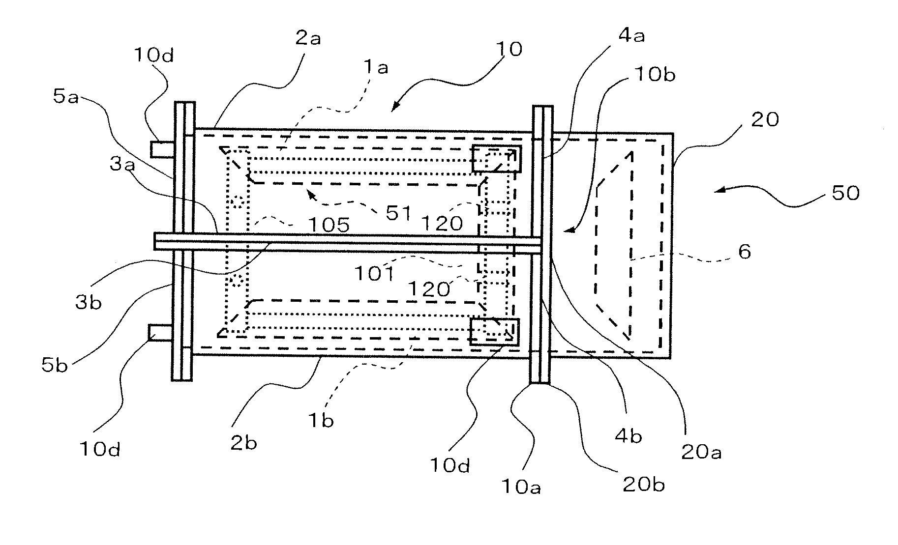
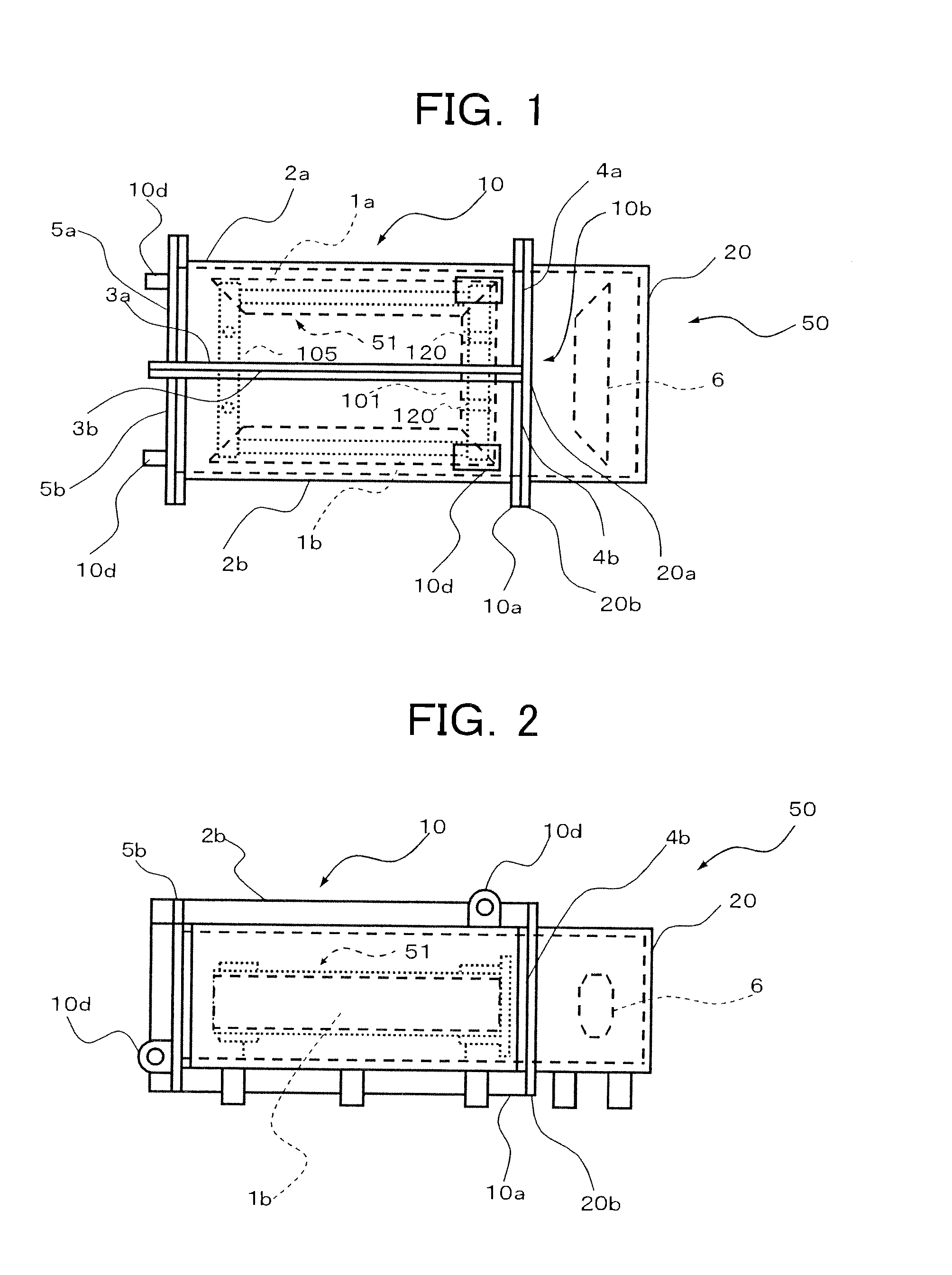
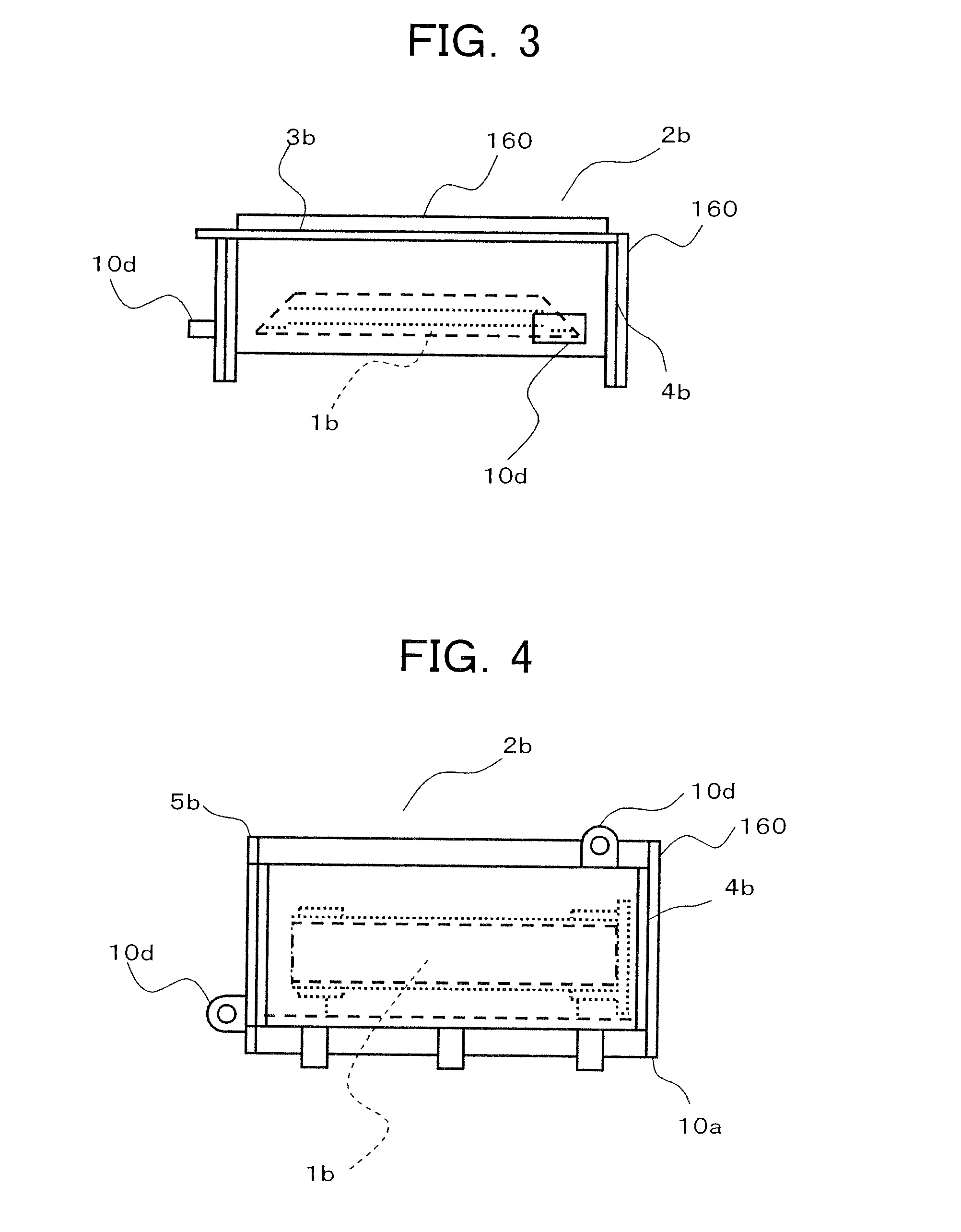
[0054]A first embodiment of a U-shaped iron core transporting / assembling method according to the present invention will be described with reference to FIGS. 1 to 7. FIG. 1 is a schematic plan view showing a state where a U-shaped iron core 51 is housed in a U-shaped iron core transporting / assembling tank 50 used in the present embodiment. FIG. 2 is a schematic front view showing the U-shaped iron core transporting / assembling tank 50 of FIG. 1. FIGS. 3 to 5 show a second leg iron core tank 2b in a state of being transported, wherein FIG. 3 is a schematic plan view, FIG. 4 is a schematic front view of FIG. 3, and FIG. 5 is a schematic side view of FIG. 3.

[0055]FIG. 6 is a schematic plan view showing a state where the U-shaped iron core 51 is housed in an erection tank 10 and a third opening portion 20a is closed. FIG. 7 is a schematic view showing a state where the erection tank 10 of FIG. 6 is erected.

[0056]As shown in FIGS. 1 and 2, the U-shaped iron core 51 is constituted by a firs...

second embodiment

[0079]A second embodiment of the U-shaped iron core transporting / assembling method according to the present invention will be described with reference to FIGS. 8 and 9. FIG. 8 shows the U-shaped iron core transporting / assembling tank 50 used in the present embodiment, which is a schematic plan view showing an example in which the lower-yoke fixing hardware 101 can be divided into a first lower-yoke fixing hardware 101a and a second lower-yoke fixing hardware 101b. FIG. 9 is a schematic side view of FIG. 8. The same reference numerals are given to the same or corresponding parts, and the description will not be repeated.

[0080]In the present embodiment, the lower-yoke fixing hardware 101 is designed so as to be divided at substantially the center thereof into a first lower-yoke fixing hardware 101a and a second lower-yoke fixing hardware 101b. The first lower-yoke fixing hardware 101a and the second lower-yoke fixing hardware 101b have a first lower-yoke fixing hardware connection se...

third embodiment

[0085]A third embodiment of the U-shaped iron core transporting / assembling method according to the present invention will be described with reference to FIGS. 10 and 11. FIG. 10 shows the U-shaped iron core transporting / assembling tank 50 used in the present embodiment, which is a schematic plan view showing an example in which the upper portion U-shaped iron core hoisting support 105 can be divided into a first upper portion U-shaped iron core hoisting support 105a and a second upper portion U-shaped iron core hoisting support 105b. FIG. 11 is a schematic side view of FIG. 10. The same reference numerals are given to the same or corresponding parts, and the description will not be repeated.

[0086]In the present embodiment, the upper portion U-shaped iron core hoisting support 105 is designed so as to be divided at substantially the center thereof into a first upper portion U-shaped iron core hoisting support 105a and a second upper portion U-shaped iron core hoisting support 105b. T...


PUM

PropertyMeasurementUnit
outer diameteraaaaaaaaaa
voltageaaaaaaaaaa
sizeaaaaaaaaaa

Abstract

Provided is a U-shaped iron core transfer/assembling method, by which a first leg iron core, a second-leg iron core and a lower-yoke iron core are housed in a first leg iron core tank, a second leg iron core tank and a lower-yoke iron core tank, respectively, and those iron cores are individually transported in sideways attitude. Next, the lower-yoke iron core is transferred into a lower-yoke iron core assembling tank. While the first leg iron core, the second leg iron core and the lower-yoke iron core being kept in the tilted postures, the first leg iron core tank, the second leg iron core tank and the lower-yoke iron core assembling tank are individually opened at their openings and are jointed to each other.

Description

CROSS REFERENCES TO RELATED APPLICATIONS[0001]This application is a continuation-in-part (GIP) application based upon the International Application PCT / JP2008 / 002180, the International Filing Date of which is Aug. 8, 2008, the entire content of which is incorporated herein by reference, and claims the benefit of priority from the prior Japanese Patent Application No. 2007-220023, filed in the Japanese Patent Office on Aug. 27, 2007, and the prior Japanese Patent Application No. 2007-279911, filed in the Japanese Patent Office on Oct. 29, 2007, the entire contents of which are incorporated herein by references.BACKGROUND OF THE INVENTION[0002]The present invention relates to a U-shaped iron core transporting / assembling method in a transformer transported in a disassembled condition and a U-shaped iron core transporting / assembling tank used in the method.[0003]In recent years, voltage to be supplied to a transmission system increases with an increase in electric power demand. Accordin...

Claims


Application Information

Patent Timeline
Patent Type & Authority Applications(United States)
IPC IPC(8): H01F7/06B23P19/00
CPCY10T29/5313Y10T29/49075Y10T29/4902H01F27/263H01F41/0206Y10T29/53165Y10T29/49819Y10T29/49078H01F27/002H01F27/245Y10T29/53265H01F41/02
Inventor SUGIHARA, MASAKISHIBATA, KEIGOYAMADA, SHIN
Owner KK TOSHIBA
Why Eureka
Try Eureka