
Sewer pipe flow through bypass device

a bypass device and sewer pipe technology, applied in sewer systems, water installations, construction, etc., can solve the problems the inflated portion of the plug or bypass can pop during use, and the problem of affecting the service life of the sewer pipe, etc., to achieve the effect of easy repair

Inactive Publication Date: 2010-06-17
SEWERKOTE
View PDF17 Cites 11 Cited by
  • Summary
  • Abstract
  • Description
  • Claims
  • Application Information

AI Technical Summary

Benefits of technology

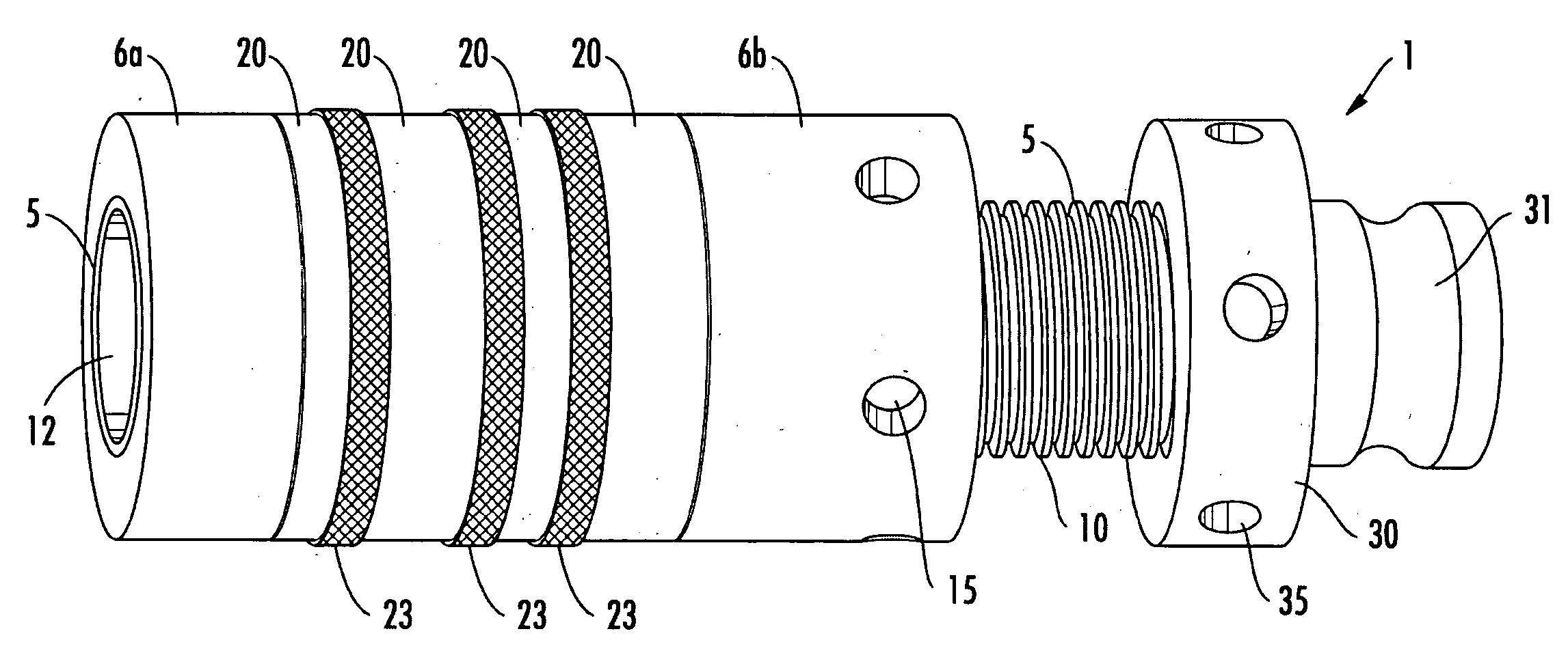
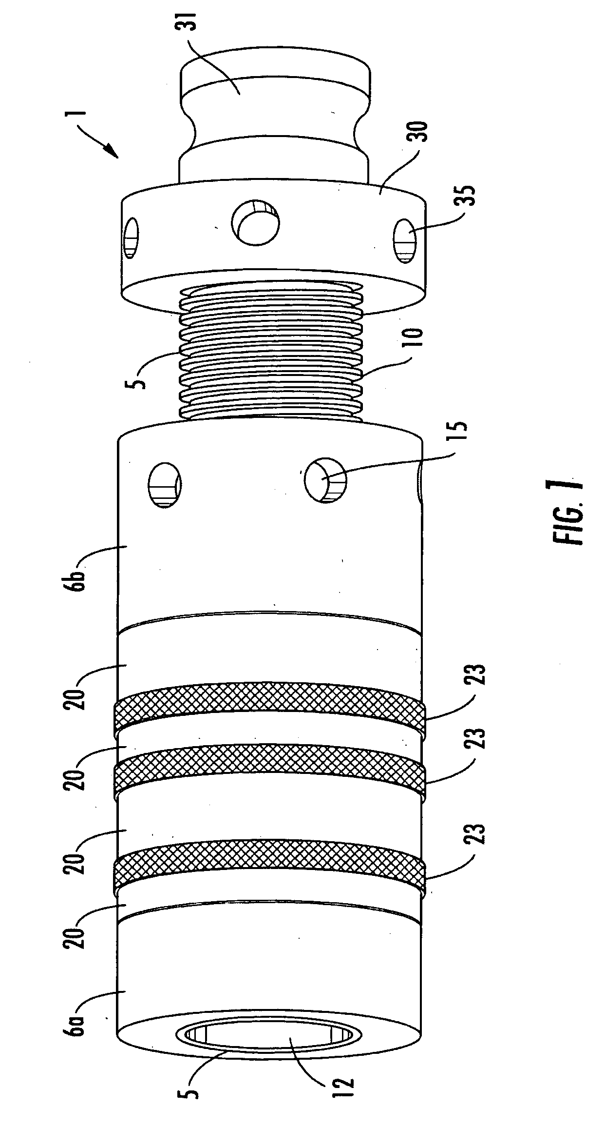
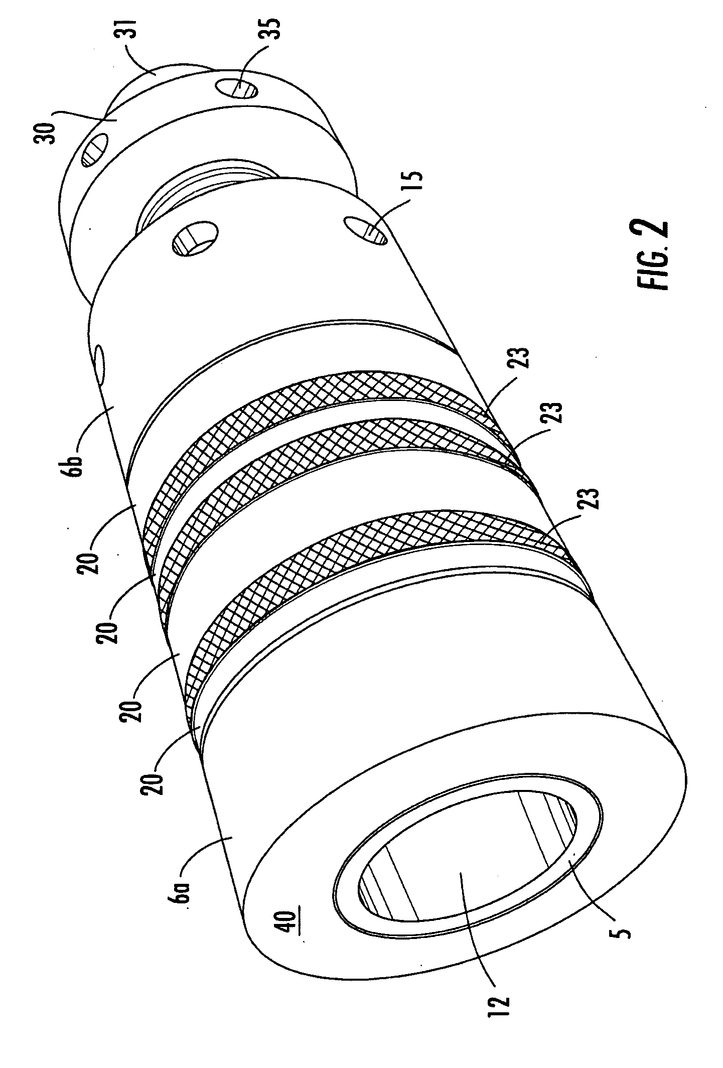
[0011]The present invention relates to a sewer bypass or plug which solves many of the problems of the prior art devices. In particular it relates to use of o rings which expand and seal the inside of the pipe. The can be sized directly to the sewer pipe being used, can be easily repaired, and do not require use of a separate pump.

Problems solved by technology

However, that is usually unacceptable since in the case of homes and businesses those facilities need to be available for continuous use and in the case of businesses must remain available or the business must close.
These types of devices, however, suffer from a number of problems.
In particular the inflated portion of the plug or bypass can pop during use.
There is no good way to see when a failure is coming so when such failures occur it is usually a costly and messy event.
In addition the inflatable devices can slowly leak leading to failure over a period of time, even though they initially form a tight seal in the sewer pipe.
The devices also require use of some form of pump which if that fails, renders the device unusable.
The devices also suffer from being relatively heavy and costly to purchase.
They are not repairable and must be replaced at frequent intervals to prevent failures.
As can be seen these devices are either not adequate for the task or rely on inflation or motorized pumping devices in order to accomplish the task of sealing or diverting effluent.
Accordingly the present state of the art is such that it inadequately provides for a safe and effective solution to the sealing or diverting of effluent from a sewer pipe opening or other pipe opening.
In addition as can be seen from these devices that they represent an expensive and time consuming way to seal or divert effluent and cheaper and easier methods would clearly be of great advantage to one skilled in the art.

Method used


Image

  • Sewer pipe flow through bypass device
  • Sewer pipe flow through bypass device
  • Sewer pipe flow through bypass device

Examples


Embodiment Construction

[0027]While this invention is susceptible to embodiment in many different forms, there is shown in the drawings and will herein be described in detail specific embodiments, with the understanding that the present disclosure of such embodiments is to be considered as an example of the principles and not intended to limit the invention to the specific embodiments shown and described. In the description below, like reference numerals are used to describe the same, similar or corresponding parts in the several views of the drawings. This detailed description defines the meaning of the terms used herein and specifically describes embodiments in order for those skilled in the art to practice the invention.

[0028]The terms “a” or “an”, as used herein, are defined as one or as more than one. The term “plurality”, as used herein, is defined as two or as more than two. The term “another”, as used herein, is defined as at least a second or more. The terms “including” and / or “having”, as used he...


PUM


Abstract

The present invention relates to a bypass device for bypassing a sewer where it exits a building. The device comprises a pass through pipe having one or more compression rings which expand under compression to seal the hollow pipe in place in a pipe exiting to a sewer.

Description

COPYRIGHT NOTICE[0001]A portion of the disclosure of this patent contains material that is subject to copyright protection. The copyright owner has no objection to the reproduction by anyone of the patent document or the patent disclosure as it appears in the Patent and Trademark Office patent files or records, but otherwise reserves all copyright rights whatsoever.BACKGROUND OF THE INVENTION[0002]1. Field of the Invention[0003]The present invention relates to a method of bypassing the main sewer when sewage exits a building or other sewage normally flushed to the main sewer. In particular the present invention is a sewer bypass device which allows the sewage from a sewage exit port to be rerouted or plugged and thus not exit into the larger main sewer.[0004]2. Description of Related Art[0005]When working on a sewer line that has active effluent sewage being deposited from surrounding buildings it is necessary in some cases to stop or divert that sewage from flowing in the sewer lin...

Claims


Application Information

Patent Timeline
Patent Type & Authority Applications(United States)
IPC IPC(8): F16L55/11
CPCE03F7/02F16L55/18F16L55/132F16L55/07
Inventor TYSON, VERNON L.
Owner SEWERKOTE
Features
  • Generate Ideas
  • Intellectual Property
  • Life Sciences
  • Materials
  • Tech Scout
  • Unparalleled Data Quality
  • Higher Quality Content
  • 60% Fewer Hallucinations
Learn More