Controlled source fracture monitoring

a controlled source and fracture technology, applied in the field of identification and imaging of fractures, can solve the problems of increasing production costs, increasing the difficulty of retrieving hydrocarbons from subterranean reservoirs, and extremely limited downhole imaging methods that transmit and receive signals from within the borehol

Active Publication Date: 2010-06-17
CONOCOPHILLIPS CO
View PDF13 Cites 60 Cited by
  • Summary
  • Abstract
  • Description
  • Claims
  • Application Information

AI Technical Summary

Benefits of technology

[0010]The proposed process is to fracture the well using standard techniques and pump proppant that has been coated with an electrically active material into the fracture per usual procedures. Following this, a wireline tool would be run into the wellbore to the fracture and an electric current sent into the fracture. Alternatively, the electric current could be introduced into the fracture from the surface via electrical connections to the casing or the mudpit. Either an AC or reversing DC current could be used to generate a time-varying signal or pulse. Since the proppant has been coated with an electrica

Problems solved by technology

Retrieving hydrocarbons from subterranean reservoirs is becoming more difficult, as existing reserves are depleted and production becomes more expensive.
Downhole imaging methods that both transmit and receive signals from within the borehole are extremely limited because detection is not separated from the formation.
Presently, no means exists to accurately assess the location (direction and distance from the wellbore) of an artificially induced frac

Method used


Image

  • Controlled source fracture monitoring
  • Controlled source fracture monitoring

Examples


Embodiment Construction

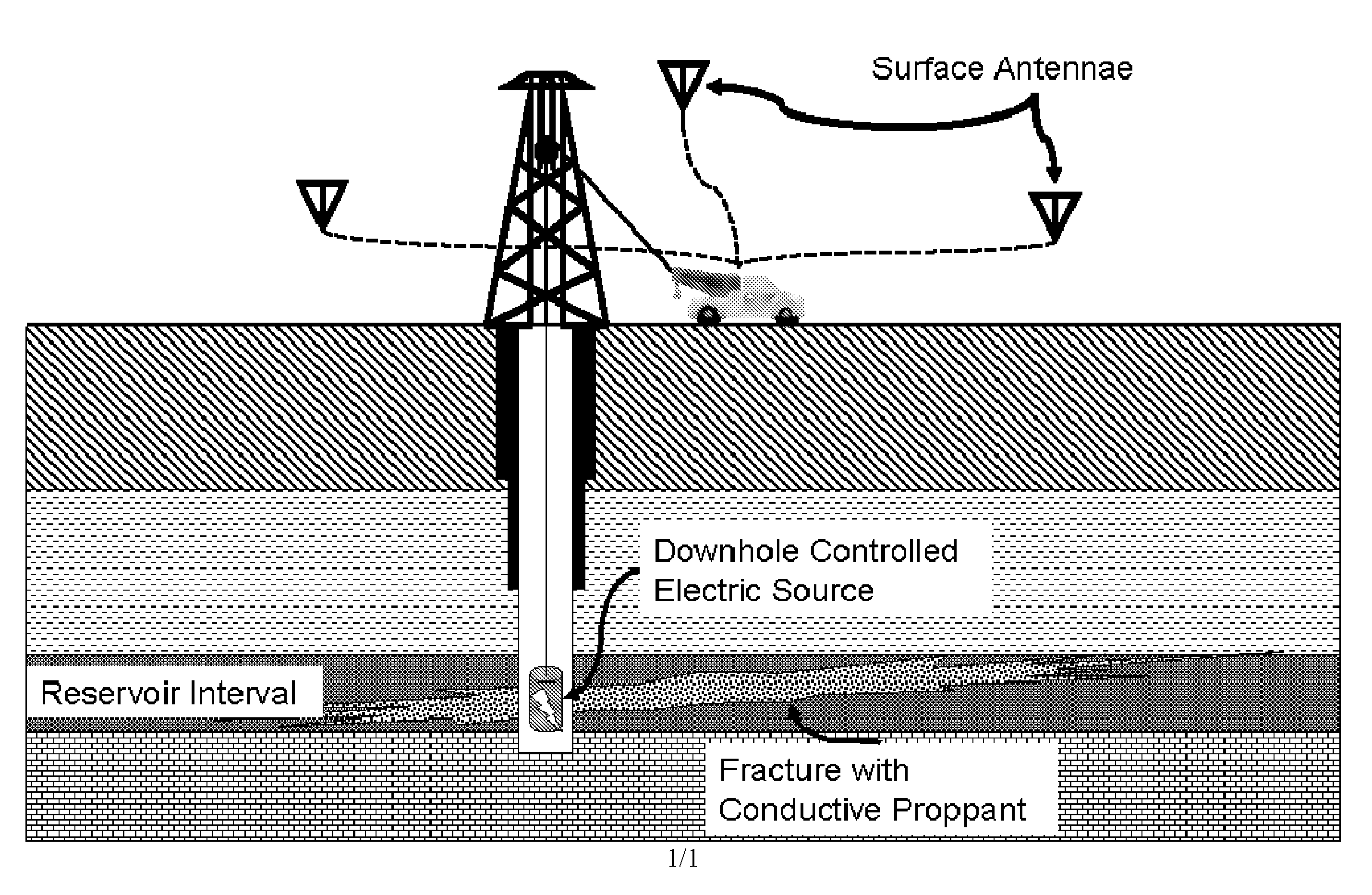
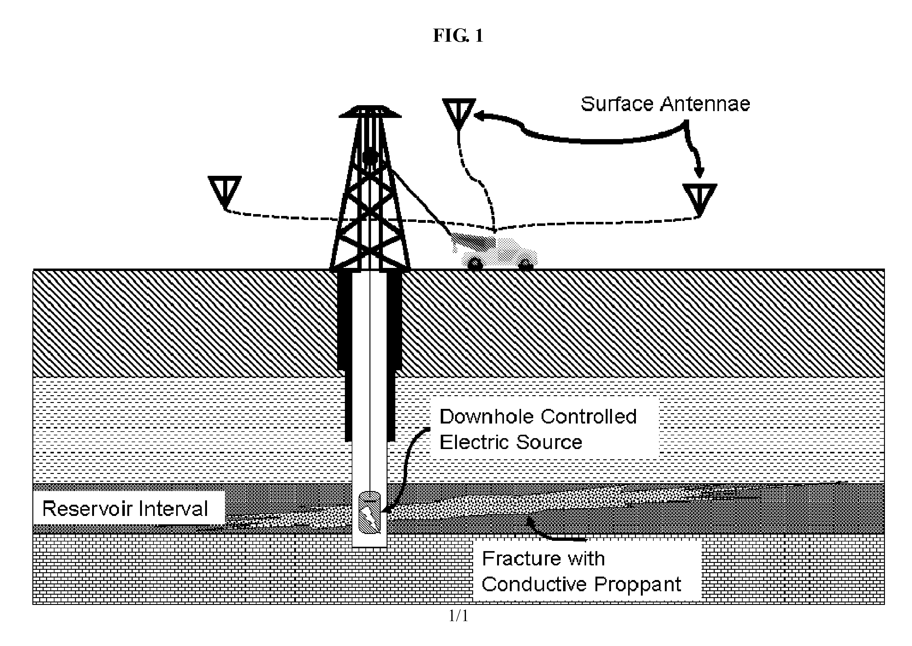
[0013]The present invention provides a method of visualizing fractures in 3- and 4-dimensions using a conductive proppant, fracture fluid, or combination proppant and fracture fluid, where electromagnetic pulses transmitted through the electric proppant-fracture fluid mixture allow direct measurement of fracture size, penetration and packing. By transmitted specific encoded electromagnetic signals through the electric proppant-fracture fluid mixture, background signals can be removed and a very accurate and detailed 3D image can be generated.

[0014]Electromagnetic detection for geophysical surveys has been established for both oilfield and mining technologies, as well as traditional academic studies (Telford, 1991; Robinson, 1988). Magnetic (B) fields are detected using magnetometers to make EM, IP, TEM, MMR from radio frequency, AC and DC electric sources. In one embodiment a fluxgate heading and orientation 3-axis high-speed digital magnetometer is used to measure magnetic fields f...


PUM


Abstract

Reservoir fractures are visualized using electrically active proppants to carry electric signals throughout the fracture. The electric signals are easily detected at the surface using RF antennae and a three-dimensional image of the fracture is generated.

Description

CROSS REFERENCE TO RELATED APPLICATIONS[0001]This application is a non-provisional application which claims benefit under 35 USC §119(e) to U.S. Provisional Application Ser. No. 61 / 121,976 filed Dec. 12, 2008, entitled “Controlled Source Fracture Monitoring” which is incorporated herein in its entirety.STATEMENT OF FEDERALLY SPONSORED RESEARCH[0002]None.FIELD OF THE DISCLOSURE[0003]The present disclosure generally relates to the identification and imaging of fractures in downhole oil well reservoirs. In one embodiment, a chargeable proppant is injected into a new fracture, electrical current through the proppant will emit a signal allowing detection and imaging of the fracture.BACKGROUND OF THE INVENTION[0004]Retrieving hydrocarbons from subterranean reservoirs is becoming more difficult, as existing reserves are depleted and production becomes more expensive. It has been estimated that mature fields account for up to 70% of the world's production or more. In order to increase produ...

Claims


Application Information

Patent Timeline
IPC IPC(8): E21B49/00
CPCE21B43/267G01V3/26
Inventor CRAMER, PETER W.EICK, PETER M.BREWER, JOEL D.
Owner CONOCOPHILLIPS CO
Why Eureka
Try Eureka